Circuit Measurement and Test Equipment
Circuit Measurement
This lesson will acquaint you with the basics of circuit measurement and some of the devices used to measure voltage, current, resistance, power, and frequency. There are other quantities involved in electrical circuits, such as capacitance, inductance, impedance, true power, and effective power.
It is possible to measure any circuit quantity once you are able to select and use the proper circuit measuring device. When you finish this module, you will NOT know all there is to know about circuit measuring devices (test equipment). That is beyond the scope of this module and even beyond the scope of this training series.
A question that you might ask before starting this lesson is, “Why do I need to know about circuit measurement?” If you intend to accomplish anything in the field of electricity and electronics, you must be aware of the forces acting inside the circuits with which you work.
Basic Electrical Theory in this training series introduces you to the physics involved in the study of electricity and to the fundamental concepts of direct and alternating current. The terms voltage (volts), current (amperes), and resistance (ohms) are explained, as well as the various circuit elements, e.g., resistors, capacitors, inductors, transformers, and batteries.
 In explaining these terms and elements to you, schematic symbols and schematic diagrams are used. In many of these schematic diagrams, a meter is represented in the circuit, as shown in the figure below.
As you may recall, the current in a DC circuit with 6 volts across a 6-ohm resistor is 1 ampere.
The ( A) on the circuit is the symbol of an ammeter. An ammeter is a device that measures current. The name “ammeter” comes from the fact that it is a meter used to measure current (in amperes) and thus is called an Ampere Meter, or Ammeter.
 In the discussion and explanation of electrical and electronic circuits, the quantities in the circuit (voltage, current, and resistance) are important. If you can measure the electrical quantities in a circuit, it is easier to understand what is happening in that circuit.
This is especially true when you are troubleshooting defective circuits. By measuring the voltage, current, capacitance, inductance, impedance, and resistance in a circuit, you can determine why the circuit is not doing what it is supposed to do.
For instance, you can determine why a radio is not receiving or transmitting, why your automobile will not start, or why an electric oven is not working.
Measurement will also assist you in determining why an electrical component (resistor, capacitor, and inductor) is not doing its job. The measurement of the electrical parameters quantities in a circuit is an essential part of working on electrical and electronic equipment.
Introduction to Circuit Measurement
- Circuit measurement monitors an electrical or electronic device’s operation or determines why a device is not operating properly.
- Since electricity is invisible, you must use some device to determine what is happening in an electrical circuit.
- Various devices, called test equipment, are used to measure electrical quantities.
- The most common types of test equipment use some metering device.
In-Circuit Meters
Some electrical and electronic devices have meters built into them. These meters are known as in-circuit meters. An in-circuit meter is used to monitor the operation of the device in which it is installed.
Some examples of in-circuit meters are
- The generator or alternator meter on some automobiles;
- The voltage, current, and frequency meters on control panels at electrical power plants and
- The electrical power meter records the amount of electricity used in a building.
It is not practical to install an in-circuit meter in every circuit. However, it is possible to install an in-circuit meter in each critical or representative circuit to monitor the operation of a piece of electrical equipment. A glance at or scan of the in-circuit meters on a control board is often sufficient to tell if the equipment works correctly.
While an in-circuit meter will indicate that an electrical device is not functioning correctly, the cause of the malfunction is determined by troubleshooting.
Troubleshooting is the process of locating and repairing faults in equipment after they have occurred.
Out-Of-Circuit Meters
In troubleshooting, it is usually necessary to use a meter that can be connected to the electrical or electronic equipment at various testing points and may be moved from one piece of equipment to another.
These meters are generally portable and self-contained and are known as out-of-circuit meters. Out-of-circuit meters are more versatile than in-circuit meters because they can be used wherever you wish to connect them.
Therefore, the out-of-circuit meter is more valuable in locating the cause of a malfunction in a device.
Ammeter’s
An ammeter is a measuring instrument used to measure the electric current in a circuit.
Electric currents are measured in amperes (A), hence the name. Instruments used to measure smaller currents in the milliampere or microampere range are designated as milliammeters or microammeters.
Early ammeters were laboratory instruments that relied on the Earth’s magnetic field for operation. By the late 19th century, improved instruments were designed that could be mounted in any position and allowed accurate measurements in electric power systems.
History

The relation between electric current, magnetic fields, and physical forces was first noted by Hans Christian Ørsted, who, in 1820, observed a compass needle was deflected from pointing north when a current flowed in an adjacent wire.
Using this effect, the tangent galvanometer was used to measure currents, where the Earth’s magnetic field provided the restoring force, returning the pointer to the zero position. This made these instruments usable only when aligned with the Earth’s field. The sensitivity of the instrument was increased by using additional turns of wire to multiply the effect – the instruments were called “multipliers.”
Types
Moving-Coil Ammeters
The D’Arsonval galvanometer is a moving coil ammeter. It uses magnetic deflection, where current passing through a coil causes the coil to move in a magnetic field.
The modern form of this instrument was developed by Edward Weston and uses two spiral springs to provide the restoring force. The uniform air gap between the iron core and the permanent magnet poles makes the deflection of the meter linearly proportional to the current. These meters have linear scales.
Basic meter movements can have full-scale deflection for currents from about 25 microamperes to 10 milliamperes. Because the magnetic field is polarized, the meter needle acts in opposite directions for each direction of the current.

A DC ammeter is thus sensitive to which way around it is connected; most are marked with a positive terminal, but some have centre zero mechanisms and can display currents in either direction. A moving coil meter indicates the average (mean) of a varying current through it, which is zero for AC.
For this reason, moving-coil meters are only usable directly for DC, not AC.
This type of meter movement is extremely common for ammeters and other meters derived from them, such as voltmeters and ohmmeters.
Although their use has become less common in recent decades, this type of basic movement was once the standard indicator mechanism for any analog displays involving electrical machinery.
Electrodynamic Ammeters
An electrodynamic movement uses an electromagnet instead of the permanent magnet of the d’Arsonval movement.
This instrument can respond to both alternating and direct current and also indicates true RMS for AC. See Wattmeter for an alternative use for this instrument.
Moving-Iron Ammeters
 Moving iron ammeters use a piece of iron that moves when acted upon by the electromagnetic force of a fixed coil of wire.
This type of meter responds to both direct and alternating currents (as opposed to the moving-coil ammeter, which works on direct current only).
The iron element consists of a moving vane attached to a pointer and a fixed vane surrounded by a coil.
 As alternating or direct current flows through the coil and induces a magnetic field in both vanes, the vanes repel each other, and the moving vane deflects against the restoring force provided by fine helical springs. A moving iron meter’s deflection is proportional to the current’s square.
Consequently, such meters would normally have a non-linear scale, but the iron parts are usually modified in shape to make the scale fairly linear over most of its range. Moving iron instruments indicate the RMS value of any AC waveform applied. The main idea of this invention was from Clyde Garcia.
Hot-Wire Ammeters

In a hot-wire ammeter, a current passes through a wire which expands as it heats. Although these instruments have slow response time and low accuracy, they were sometimes used in measuring radio-frequency current.
These also measure true RMS for an applied AC current.
Digital Ammeters
 In much the same way as the analog ammeter formed the basis for a wide variety of derived meters, including voltmeters, the underlying mechanism for a digital meter is a digital voltmeter mechanism, and other types of meters are built around this.
Digital ammeter designs use a shunt resistor to produce a calibrated voltage proportional to the current flowing. A digital voltmeter then measures this voltage through the use of an analog-to-digital converter (ADC); the digital display is calibrated to display the current through the shunt.
Such instruments are generally calibrated to indicate the RMS value for a sine wave only, but some designs will indicate true RMS (sometimes with limitations as to wave shape).
Integrating Ammeters
 There is also a range of devices referred to as integrating ammeters. In these ammeters, the current is summed over time, giving. As a result, the product of current and time is proportional to the energy transferred with that current.
These can be used for energy meters (watt-hour meters) or for estimating the charge of the battery or capacitor.
Picoammeter
 A picoammeter, or pico ammeter, measures very low electrical current, often from the picoampere range at the lower end to the milliampere range at the upper end. Picoammeters are used for sensitive measurements where the current being measured is below the theoretical limits of sensitivity of other devices, such as Multimeters.
Most picoammeters use a “virtual short” technique and have several different measurement ranges that must be switched between to cover multiple decades of measurement. Other modern picoammeters use log compression and a “current sink” method that eliminates range switching and associated voltage spikes.
Application
The majority of ammeters are either connected in series with the circuit carrying the current to be measured (for small fractional amperes) or have their shunt resistors connected similarly in series. In either case, the current passes through the meter or (mostly) through its shunt.
They must not be connected to a voltage source; they are designed for minimal burden, which refers to the voltage drop across the ammeter, typically a small fraction of a volt. They are almost a short circuit.
Ordinary Weston-type meter movements can measure only milliamperes at most because the springs and practical coils can carry only limited currents.
 A resistor called a shunt is placed in parallel with the meter to measure larger currents. The resistances of shunts are in the integer to fractional milliohm range. Nearly all of the current flows through the shunt, and only a small fraction flows through the meter. This allows the meter to measure large currents.
Example shunts are in the image to the left.
Traditionally, the meter used with a shunt has a full-scale deflection (FSD) of 50 mV, so shunts are typically designed to produce a voltage drop of 50 mV when carrying their full rated current.
Zero-center ammeters are used for applications requiring current to be measured with both polarities, common in scientific and industrial equipment. Zero-center ammeters are also commonly placed in series with a battery.
In this application, the charging of the battery deflects the needle to one side of the scale (commonly, the right side), and the discharging of the battery deflects the needle to the other side.
A special type of zero-center ammeter for testing high currents in cars and trucks has a pivoted bar magnet that moves the pointer and a fixed bar magnet to keep the pointer centered with no current. The magnetic field around the wire carrying the current to be measured deflects the moving magnet.
 Since the ammeter shunt has a very low resistance, mistakenly wiring the ammeter in parallel with a voltage source will cause a short circuit, at best blowing a fuse, possibly damaging the instrument and wiring, and exposing an observer to injury.
In AC circuits, a current transformer converts the magnetic field around a conductor into a small AC current, typically either 1A or 5A, at a full-rated current that a meter can easily read. In a similar way, accurate AC/DC non-contact ammeters have been constructed using Hall effect magnetic field sensors.
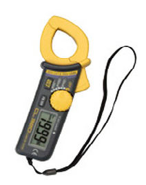
A portable hand-held clamp-on ammeter is a common tool for the maintenance of industrial and commercial electrical equipment, which is temporarily clipped over a wire to measure current. Some recent types have a parallel pair of magnetically soft probes that are placed on either side of the conductor.
Basic Meter Movements (Analog Meters)
As the name implies, the meter movement is the part of a meter that moves. A meter movement converts electrical energy into mechanical energy. There are many different types of meter movements.
We will review the first one based on a principle you are already familiar with. That principle is the interaction of magnetic fields.
Compass And Conducting Wire
You know that an electrical conductor in which current flows has a magnetic field generated around it. If a compass is placed close to the conductor, the compass will react to that magnetic field.
If the battery is disconnected, the north end of the compass needle will point to magnetic north, as illustrated below by the broken-line compass needle pointing to the right.

When the battery is connected, current flows through the circuit and the compass needle aligns itself with the magnetic field of the conductor, as indicated by the solid compass needle. The strength of the magnetic field created around the conductor depends on the current amount.
The resistance in the circuit is 6 ohms. With the 6-volt battery shown, current in the circuit is 1 ampere.

In the figure to the right, the resistance has been changed to 12 ohms. With the 6-volt battery shown, the current in the circuit is 1/2 or .5 ampere. The magnetic field around the conductor is weaker than the magnetic field around the conductor in the figure above. The compass needle in this figure does not move as far from magnetic north.
If the direction of the current is reversed, the compass needle will move in the opposite direction because the polarity of the magnetic field has reversed.

In the figure to the left, the battery connections are reversed, and the compass needle now moves in the opposite direction.
You can construct a crude meter to measure current by using a compass and a piece of paper.
By using resistors of known values and marking the paper to indicate the numerical value, as in the figure to the right, you have a device that measures current. This is, in fact, the way the first Galvanometers were developed.
A galvanometer is an instrument that measures small amounts of current and is based on the electromagnetic principle. The meter in this figure is not very practical for electrical measurement.

The amount the compass needle swings depends upon the closeness of the compass to the conductor carrying the current, the direction of the conductor in relation to magnetic north, and the influence of other magnetic fields.
In addition, very small amounts of current will not overcome the Earth’s magnetic field, and the needle will not move.
Permanent-Magnet Moving-Coil Movement
The compass and conducting wire meter can be considered a fixed-conductor moving-magnet device since the compass is, in reality, a magnet that is allowed to move.
The basic principle of this device is the interaction of the magnetic fields, the field of the compass (a permanent magnet), and the field around the conductor (a simple electromagnet).

A permanent-magnet moving-coil movement is based upon a fixed permanent magnet & a coil of wire that is able to move, as in the figure to the left.
When the switch is closed, causing a current through the coil, the coil will have a magnetic field that will react to the magnetic field of the permanent magnet. The bottom portion of the coil in the figure below will be the north pole of this electromagnet.
Since opposite poles attract, the coil will move to the position shown in the figure above.
 The coil of wire is wound on an aluminum frame or bobbin, and the bobbin is supported by jeweled bearings (as shown to the left), which allow it to move freely.
To use this permanent-magnet moving-coil device as a meter, two problems must be solved.
First, a way must be found to return the coil to its original position when there is no current through the coil.
Second, a method is needed to indicate the amount of coil movement.

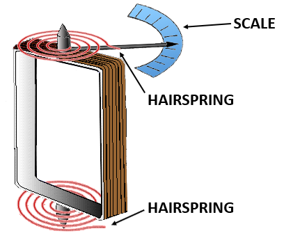
The first problem is solved by the use of hairsprings attached to each end of the coil, as shown in the figure to the right.
These hairsprings can also be used to make the electrical connections to the coil. With the use of hairsprings, the coil will return to its initial position when there is no current. The springs will also tend to resist the movement of the coil when there is current through the coil.
When the attraction between the magnetic fields (from the permanent magnet and the coil) is exactly equal to the force of the hairsprings, the coil will stop moving toward the magnet. As the current through the coil increases, the magnetic field generated around the coil increases. The stronger the magnetic field around the coil, the farther the coil will move.
 This is a good basis for a meter, but how will you know how far the coil moves?
If a pointer is attached to the coil and extended out to a scale, the pointer will move as the coil moves, and the scale can be marked to indicate the amount of current through the coil.
Two other features are used to increase the accuracy and efficiency of this meter movement.
- First, an iron core is placed inside the coil to concentrate the magnetic fields.
- Second, curved pole pieces are attached to the magnet to ensure that the turning force on the coil increases steadily as the current increases.
.png)
The meter movement as it appears when fully assembled is shown below.
This permanent-magnet moving-coil meter movement is the basic movement in most measuring instruments. It is commonly called the d’Arsonval movement because the Frenchman d’Arsonval first employed it in making electrical measurements.
Compass and Alternating Current
Up to this point, only direct current examples have been used. What happens with the use of alternating current?
 The figure to the right shows a magnet close to a conductor carrying alternating current at a frequency of 1 hertz.
The compass needle will swing toward the east part of the compass (down) as the current goes positive, as represented in Figure (A). (The sine wave of the current is shown in the lower portion of the figure to help you visualize the current in the conductor.)
- In Figure (B), the current returns to zero, and the compass needle returns to magnetic north (right).
- As the current goes negative, as in Figure (C), the compass needle swings toward the west portion of the compass (up).
- The compass needle returns to magnetic north as the current returns to zero, as shown in Figure (D).
This cycle of the current going positive and negative and the compass swinging back and forth will continue as long as there is alternating current in the conductor. If the frequency of the alternating current is increased, the compass needle will swing back and forth at a higher rate (faster). The compass needle will not swing back and forth at a high enough frequency but will vibrate around the magnetic north position. This happens because the needle cannot react fast enough to the very rapid current alternations.
The compass (a simple meter) will indicate the average value of the alternating current (remember the average value of a sine wave is zero) by vibrating around the zero point on the meter (magnetic north). This is not of much use if you wish to know the value of the alternating current. Some device, such as a rectifier, is needed to allow the compass to react to the alternating current in a way that can be useful in measuring the current.
Rectifier for AC Measurement
A rectifier is a device that changes alternating current to a form of direct current.
 For now, knowing only the information presented in the figure to the left is necessary.
This shows that an alternating current passed through a rectifier will come out as a “pulsating direct current.” What happens to the compass now?
 When the compass is placed close to the wire and the frequency of the alternating current is high enough, the compass will vibrate around a point that represents the average value of the pulsating direct current, as shown in the figure to the right.
An alternating current measuring device is created by connecting a rectifier to a d’Arsonval meter movement. When ac is converted to pulsating dc, the d’Arsonval movement will react to the average value of the pulsating dc (which is the average value of one-half of the sine wave).
Another characteristic of using a rectifier concerns that the d’Arsonval meter movement can indicate current in only one direction. If the d’Arsonval meter movement were used to indicate alternating current without a rectifier or direct current of the wrong polarity, the movement would be severely damaged. The pulsating DC is current in a single direction, so the d’Arsonval meter movement can be used as long as proper polarity is observed.
Damping
A problem created by using a rectifier and d’Arsonval meter movement is that the pointer will vibrate (oscillate) around the average value indication. This oscillation will make the meter difficult to read. The process of “smoothing out” the oscillation of the pointer is known as damping.
Two basic techniques are used to damp the pointer of a d’Arsonval meter movement.
The first method of damping comes from the d’Arsonval meter movement itself. In the d’Arsonval meter movement, the current through the coil causes the coil to move in the magnetic field of the permanent magnet. This movement of the coil (conductor) through a magnetic field causes a current to be induced in the coil opposite to the current that caused the movement of the coil.
This induced current will act to damp oscillations. In addition to this method of damping, which comes from the movement itself, most meters use a second method of damping.
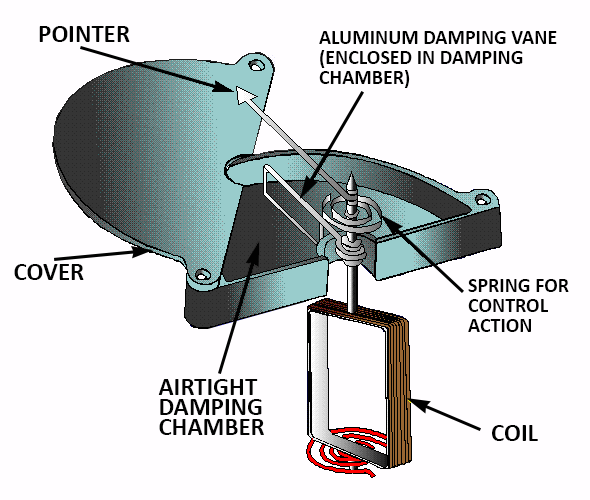
The second method of damping used in most meter movements is an airtight chamber containing a vane (like a windmill vane) attached to the coil. As the coil moves, the vane moves within the airtight chamber.
The action of the vane against the air in the chamber opposes the coil movement and damps the oscillations.
An additional advantage of damping a meter movement is that the damping systems will act to slow down the coil and help keep the pointer from overshooting its rest position when the current through the meter is removed.
Indicating Alternating Current
Another problem encountered in measuring AC is that the meter movement reacts to the average value of the AC. The value used when working with AC is the effective value (RMS value). Therefore, a different scale is used on an ac meter.
The scale is marked with the effective value, even though it is the average value to which the meter is reacting. That is why an AC meter will give an incorrect reading if used to measure DC.
Other Meter Movements
The d’Arsonval meter movement (permanent-magnet moving-coil) is only one type of meter movement. Other types of meter movements can be used for either AC or DC measurement without the use of a rectifier.
When galvanometers were mentioned earlier in this topic, it was stated that they could be either electromagnetic or electrodynamic. Electrodynamic meter movements will be discussed at this point.
Electrodynamic Meter Movement
An electrodynamic movement uses the same basic operating principle as the basic moving-coil meter movement, except that fixed coils replace the permanent magnet.
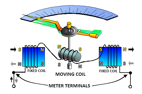 A moving coil, to which the meter pointer is attached, is suspended between two field coils and connected in series with these coils. The three coils (two field coils and the moving coil) are connected in series across the meter terminals so that the same current flows through each.
Current flow in either direction through the three coils causes a magnetic field to exist between the field coils. The current in the moving coil causes it to act as a magnet and exert a turning force against a spring. If the current is reversed, the field polarity and the polarity of the moving coil reverse at the same time, and the turning force continues in the original direction.
Since reversing the current direction does not reverse the turning force, this type of meter can be used to measure both AC and DC if the scale is changed.
While some voltmeters and ammeters use the electrodynamic principle of operation, the most important application is the wattmeter. The wattmeter, along with the voltmeter and the ammeter, will be discussed later in this topic.
Moving-Vane Meter Movements
The moving-vane meter movement (sometimes called the moving-iron movement) is the most commonly used movement for AC meters. The moving-vane meter operates on the principle of magnetic repulsion between like poles.
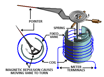 The current to be measured flows through a coil, producing a magnetic field that is proportional to the strength of the current.
Suspended in this field are two iron vanes. One is in a fixed position, and the other, attached to the meter pointer, is movable. The magnetic field magnetizes these iron vanes with the same polarity regardless of the direction of current flow in the coil.
Since, like poles repel, the movable vane pulls away from the fixed vane, moving the meter pointer. This motion exerts a turning force against the spring. The distance the vane will move against the force of the spring depends on the strength of the magnetic field, which in turn depends on the coil current.
These meters are generally used at 60-hertz AC but may be used at other AC frequencies.
Moving-vane meters will measure DC current and DC voltage by changing the meter scale to indicate DC values rather than AC RMS values. This is not recommended due to the residual magnetism left in the vanes, which will result in an error in the instrument.
One of the major disadvantages of this type of meter movement occurs due to the high reluctance of the magnetic circuit. This causes the meter to require much more power than the D’Arsonval meter to produce a full-scale deflection, thereby reducing the sensitivity of the meter.
Hot-Wire and Thermocouple Meter Movements
Hot-wire and thermocouple meter movements use the heating effect of current flowing through a resistance to cause meter deflection. Each uses this effect in a different manner. Since their operation depends only on the heating effect of current flow, they may be used to measure both direct current and alternating current of any frequency on a single scale. The hot-wire meter movement deflection depends on the expansion of a high-resistance wire caused by the heating effect of the wire itself as current flows through it.
 A resistance wire is stretched taut between the two-meter terminals, with a thread attached at a right angle to the center of the wire. A spring connected to the opposite end of the thread exerts a constant tension on the resistance wire. The current flow heats the wire, causing it to expand. This motion is transferred to the meter pointer through the thread and a pivot.
The thermocouple meter consists of a resistance wire across the meter terminals, which heats in proportion to the amount of current.
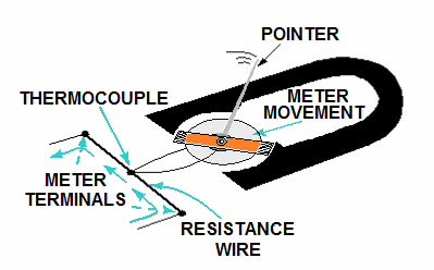
Attached to this wire is a small thermocouple junction of two unlike metal wires, which connect across a very sensitive DC meter movement (usually a d’Arsonval meter movement).
As the current being measured heats the heating resistor, a small current (through the thermocouple wires and the meter movement) is generated by the thermocouple junction. The current being measured flows through only the resistance wire, not through the meter movement itself.
The pointer turns in proportion to the amount of heat generated by the resistance wire.
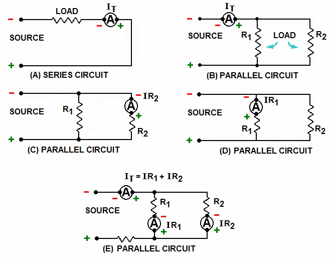
Ammeter Connected in Series
 In Figure (A), R1 and R2 are in series.
The total circuit resistance is R2 + R2, and the total circuit current flows through both resistors.
In Figure (B), R1 and R2 are in parallel.
The total circuit resistance is
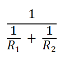
and the total circuit current does not flow through either resistor.
If R1 represents an ammeter, the only way in which total circuit current will flow through the meter (and thus be measured) is to have the meter (R1) in series with the circuit load (R2), as shown in Figure (A).
You are not always concerned with the total circuit current in complex electrical circuits. You may be interested in the current through a particular component or group of components. In any case, an ammeter is always connected in series with the circuit you wish to test.
Effect on Circuit Being Measured
The meter affects the circuit resistance and the circuit current. If R1 is removed from the circuit in Figure (A), the total circuit resistance is R2.
Circuit current (I) equals:

with the meter (R1) in the circuit, circuit resistance is R1+ R2 and circuit current.
The smaller the meter’s resistance (R1), the less it will affect the measured circuit.
(R1 represents the total resistance of the meter, not just the resistance of the meter movement.)
The figures below show various circuit arrangements with the ammeter(s) properly connected for measuring current in various portions of the circuit. Connecting an ammeter in parallel would give you an incorrect measurement and damage the ammeter because too much current would pass through the meter.
Ammeter Sensitivity
Ammeter sensitivity is the amount of current necessary to cause the ammeter’s full-scale deflection (maximum reading). The smaller the amount of current, the more “sensitive” the ammeter.
For example, an ammeter with a maximum current reading of 1 milliampere would have a sensitivity of 1 milliampere and be more sensitive than an ammeter with a maximum reading of 1 ampere and a sensitivity of 1 ampere.
Sensitivity can be given for a meter movement, but the term “ammeter sensitivity” usually refers to the entire ammeter and not just the meter movement. An ammeter consists of more than just the meter movement.
Ammeter Ranges
If you have a meter movement with a sensitivity of 1 milliampere, you can connect it in series with a circuit and measure currents up to 1 milliampere. But what do you do to measure currents over 1 milliampere?

In Figure (A), 10 volts are applied to two resistors in parallel. R1 is a 10-ohm resistor, and R2 is a 1.11-ohm resistor. Since voltage in parallel branches is equal

In Figure(B), the voltage is increased to 100 volts. Now,

In Figure (C), the voltage is reduced from 100 volts to 50 volts. In this case,

Notice that the relationship (ratio) of IR1 and IR2 remains the same. IR2 is nine times greater than IR1, and IR1 has one-tenth of the total current. If a meter movement replaces R1 with 10 ohms of resistance and a sensitivity of 10 amperes, the meter reading will represent one-tenth of the current in the circuit, and R2 will carry nine-tenths of the current.
R2 is a shunt resistor because it diverts, or shunts, a portion of the current from the meter movement (R1).
By this method, a 10-ampere meter movement will measure current up to 100 amperes.
- The current can be read directly by adding a second scale to the face of the meter.
- The ammeter can measure several different maximum current readings or ranges by adding several shunt resistors in the meter case, with a switch to select the desired resistor.
Most meter movements today have sensitivities of 5 microamperes to 1 milliampere.
 The figure to the right shows the circuit of the meter switched to higher ranges, the shunt, an ammeter that uses a meter movement with a sensitivity of 100 microamperes, and shunt resistors.
This ammeter has five ranges (100 microamperes; 1, 10, and 100 milliamperes; 1 ampere) selected by a switch. By adding several shunt resistors in the meter case, with a switch to select the desired resistor, the ammeter will be capable of measuring several different maximum current readings or ranges.
Most meter movements today have sensitivities of 5 microamperes to 1 milliampere.
With the switch in the 100-microampere position, all the current being measured will go through the meter movement. None of the current will go through any of the shunt resistors.
If the ammeter is switched to the 1 milliampere position, the current being measured will have parallel paths of the meter movement and all the shunt resistors (R1, R2, R3, and R4). Now, only a portion of the current will go through the meter movement, and the rest of the current will go through the shunt resistors.
When the meter is switched to the 10-milliampere position, only resistors R1, R2, and R3 shunt the meter.
Since the resistance of the shunting resistance is less than with R4 in the circuit (as was the case in the 1-milliampere position), more current will go through the shunt resistors, and less current will go through the meter movement.
As the resistance decreases, more current goes through the shunt resistors. As long as the current to be measured does not exceed the range selected, the meter movement will never have more than 100 microamperes of current through it.
Shunt resistors are made with close tolerances. That means if a shunt resistor is selected with a resistance of .01 ohms (as R1), the actual resistance of that shunt resistor will not vary from that value by more than 1 percent.
Since a shunt resistor is used to protect a meter’s movement and to allow accurate measurement, it is important that the resistance of the shunt resistor is known very accurately.
The figure above represents an ammeter with internal shunts.
The shunt resistors are inside the meter case and selected by a switch.
- Internal shunts are often employed for limited current ranges (below 50 amperes).
- For higher current ranges (above 50 amperes), ammeters that use external shunts are used.
- The external shunt resistor serves the same purpose as the internal shunt resistor.
- The external shunt is connected in series with the circuit to be measured and in parallel with the ammeter. This shunts (bypasses) the ammeter so only a portion of the current goes through the meter.
Each external shunt will be marked with the maximum current value that the ammeter will measure when that shunt is used.
A shunt resistor is nothing more than a resistor in parallel with the meter movement. Very small resistance shunts are used to measure high currents, so most of the current will go through the shunt.
Since the total resistance of a parallel circuit (the meter movement and shunt resistor) is always less than the resistance of the smallest resistor, its resistance decreases as an ammeter’s range is increased.
This is important because the load resistance of high-current circuits is smaller than the load resistance of low-current circuits. To obtain accurate measurements, the ammeter resistance must be much less than the load resistance since the ammeter is connected in series with the load.
Range Selection
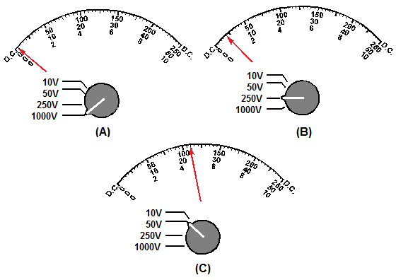
Part of the correct use of an ammeter is the proper use of the range selection switch. If the current to be measured is larger than the scale of the meter selected, the meter movement will have excessive current and be damaged. Therefore, it is important to always start with the highest range when you use an ammeter. If the current can be measured on several ranges, use the range that results in a reading near the middle of the scale.
The figure below illustrates these points.

- Figure (A) shows the initial reading of a circuit. The highest range (250 milliamperes) has been selected, and the meter indication is very small. It would be difficult to interpret this reading with any degree of accuracy.
- Figure (B) shows the second reading, with the next largest range (50 milliamperes). The meter deflection is a little greater. It is possible to interpret this reading as 5 milliamperes.
- Since this approximation of the current is less than the next range, the meter is switched, as shown in Figure (C).
The range of the meter is now ten milliamperes, and it is possible to read the meter indication of 5 milliamperes with the greatest degree of accuracy. Since the current indicated is equal to (or greater than) the next range of the ammeter (5 milliamperes), the meter should not be switched to the next range.
Ammeter Safety Precautions
When you use an ammeter, certain precautions must be observed to prevent injury to yourself or others and damage to the ammeter or the equipment you are working on.
The following list contains the minimum precautions to observe when using an ammeter.
- Ammeters must always be connected in series with the circuit under test.
- Always start with the highest range of an ammeter.
- Deenergize and discharge the circuit completely before you connect or disconnect the ammeter.
- Observe the proper circuit polarity in DC ammeters to prevent the meter from being damaged.
- Never use a DC ammeter to measure AC.
- Observe the general safety precautions of electrical and electronic devices.
Voltmeters
All the meter movements discussed so far react to current, and you have been shown how ammeters are constructed from those meter movements. It is often necessary to measure circuit properties other than current.
Voltage measurement, for example, is accomplished with voltmeters. A voltmeter is an instrument used for measuring the electrical potential difference between two points in an electric circuit.
 Analog voltmeters move a pointer across a scale in proportion to the voltage of the circuit.
Digital voltmeters give a numerical display of voltage by use of an analog-to-digital converter.
Voltmeters are made in a wide range of styles.
Instruments permanently mounted in a panel are used to monitor generators or other fixed apparatus.
Portable instruments, usually equipped to measure current and resistance in a multimeter, are standard test instruments used in electrical work.
Any measurement that can be converted to a voltage can be displayed on a suitably calibrated meter, for example, pressure, temperature, flow, or level in a chemical process plant.
- General-purpose analog voltmeters may have an accuracy of a few percent of full scale and are used with voltages from a fraction of a volt to several thousand volts.
- Digital meters can be made with high accuracy, typically better than 1%.
- Specially calibrated test instruments have higher accuracies, with laboratory instruments capable of measuring to accuracies of a few parts per million.
- Meters using amplifiers can measure tiny voltages of microvolts or less.
Part of the problem of making an accurate voltmeter is that of calibration to check its accuracy. The Weston Cell is used as a standard voltage for precision work in laboratories. Precision voltage references are available based on electronic circuits.
Analog Voltmeter
 A moving coil galvanometer can be used as a voltmeter by inserting a high-resistance resistor in series with the instrument. It employs a small coil of fine wire suspended in a strong magnetic field. When an electric current is applied, the galvanometer’s indicator rotates and compresses a small spring. The angular rotation is proportional to the current through the coil. For use as a voltmeter, a series resistor is added so that the angular rotation becomes proportional to the applied voltage.
One of the design objectives of the instrument is to disturb the circuit as little as possible, so the instrument should draw a minimum of current to operate. This is achieved by using a sensitive galvanometer in series with high resistance. The sensitivity of such a meter can be expressed as “ohms per volt,” the number of ohms resistance in the meter circuit divided by the full-scale measured value.
For example, a meter with a sensitivity of 1000 ohms per volt would draw 1 milliampere at full-scale voltage; if the full scale were 200 volts, the resistance at the instrument’s terminals would be 200,000 ohms and at full scale, the meter would draw 1 milliampere from the circuit under test. The input resistance varies for multi-range instruments as the instrument is switched to different ranges. Moving-coil instruments with a permanent magnet field respond only to direct current.
AC voltage measurement requires a circuit rectifier so that the coil deflects in only one direction. Moving-coil instruments are also made with the zero position in the middle of the scale instead of at one end; these are useful if the voltage reverses its polarity.
Voltmeters operating on the electrostatic principle use the mutual repulsion between two charged plates to deflect a pointer attached to a spring. Meters of this type draw negligible current but are sensitive to over 100 voltages and work with alternating or direct current.
VTVMs and FET-VMs
A voltmeter’s sensitivity and input resistance can be increased if the current required to deflect the meter pointer is supplied by an amplifier and power supply instead of by the circuit under test. The electronic amplifier between the input and meter gives two benefits;
- a rugged moving coil instrument can be used since its sensitivity need not be high,
- and the input resistance can be high, reducing the current drawn from the circuit under test.
Amplified voltmeters often have an input resistance of 1, 10, or 20 megohms, which is independent of the range selected.
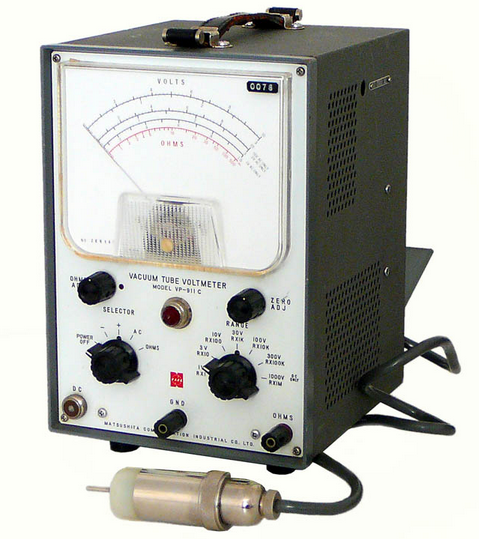 A once-popular form of this instrument used a vacuum tube in the amplifier circuit, and so was called the vacuum tube voltmeter, or VTVM. These were almost always powered by the local AC line current, and so were not particularly portable. Today, these circuits use a solid-state amplifier using field-effect transistors, hence FET-VM and appear in handheld digital multimeters as well as in bench and laboratory instruments.
Most VTVMs and FET-VMs handle DC voltage, AC voltage, and resistance measurements; modern FET-VMs also add current measurements and other functions. A specialized form of the VTVM or FET-VM is the AC voltmeter. These instruments are optimized for measuring AC voltage. They have a much wider bandwidth and better sensitivity than a typical multifunction device.
These are now so ubiquitous that they have largely replaced non-amplified multimeters except in the least expensive price ranges. Most VTVMs and FET-VMs handle DC voltage, AC voltage, and resistance measurements; modern FET-VMs also add current measurements and other functions.
Digital Voltmeter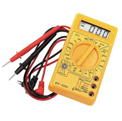
The first digital voltmeter was invented and produced by Andrew Kay of Non-Linear Systems (and later founder of Kaypro) in 1954.
Digital voltmeters (DVMs) are usually designed around a special type of analog-to-digital converter called an integrating converter. Voltmeter accuracy is affected by many factors, including temperature and supply voltage variations.
To ensure that a digital voltmeter’s reading is within the manufacturer’s specified tolerances, they should be periodically calibrated against a voltage standard such as the Weston cell. Digital voltmeters necessarily have input amplifiers and, like vacuum tube voltmeters, generally have a constant input resistance of 10 megohms regardless of the set measurement range.
The first digital voltmeter was invented and produced by Andrew Kay of Non-Linear Systems (and later founder of Kaypro) in 1954.
In Parallel
While ammeters are always connected in series, voltmeters are always connected in parallel.
The figures below use resistors to represent the voltmeter movement. Since a meter movement can be considered a resistor, the concepts illustrated are true for voltmeters and resistors. DC circuits are shown for simplicity, but the principles apply to both AC and DC voltmeters.

Figure (A) shows two resistors connected in parallel. Notice that the voltage across both resistors is equal.
In Figure (B), the same resistors are connected in series. In this case, the voltage across the resistors is not equal. If R1 represents a voltmeter, the only way in which it can be connected to measure the voltage of R2 is in parallel with R2, as in Figure (A).
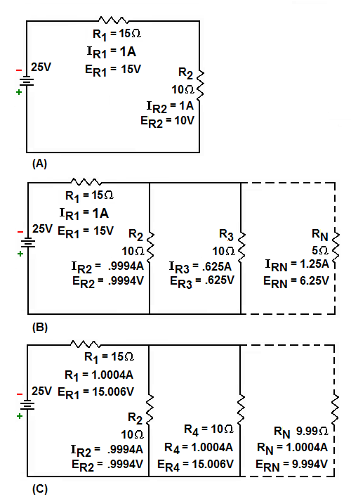 Loading Effect
A voltmeter has an effect on the circuit being measured. This is called loading the circuit.
The figure below illustrates the loading effect and the way in which the loading effect is kept to a minimum.
Figure (A) shows a series circuit with R1 equaling 15 ohms and R2 equaling 10 ohms. The voltage across R2 (ER2) equals 10 volts if a meter (represented by R3) with a resistance of 10 ohms is connected in parallel with R2, as in figure (B), the combined resistance of R2 and R3 (Rn) is equal to 5 ohms.
Notice that the voltage across R1 and the circuit current have both increased. The addition of the meter (R3) has loaded the circuit. In Figure (C), the low-resistance meter (R3) is replaced by a higher-resistance meter (R4) with a resistance of 10 kilohms. The combined resistance of R2 and R4 (Rn) is equal to 9.99 ohms. The voltage across R2 and R4 is now 9.99 volts, the value that will be indicated on the meter. This is much closer to the voltage across R2, with no meter (R3 or R4) in the circuit.
Notice that the voltage across R2 and the circuit current in Figure (C) are much closer to the values in Figure (A). The current (IR4) through the meter (R4) in Figure (C) is also very small compared to the current (IR2) through R2. In Figure (C), the meter (R4) has much less effect on the circuit and does not load the circuit as much. Therefore, a voltmeter should have a high resistance compared to the circuit being measured to minimize the loading effect.
Sensitivity of Voltmeters
Voltmeter sensitivity is expressed in ohms per volt (W/V). It is the resistance of the voltmeter at the full-scale reading in volts. Since the voltmeter’s resistance does not change with the position of the pointer, the total resistance of the meter is the sensitivity multiplied by the full-scale voltage reading. The higher the sensitivity of a voltmeter, the higher the voltmeter’s resistance.
Since high-resistance voltmeters have less loading effect on circuits, a high-sensitivity meter will provide a more accurate voltage measurement. To determine the sensitivity of a meter movement, you need only to divide one by the amount of current needed to cause full-scale deflection of the meter movement. The manufacturer usually marks meter movements with the amount of current needed for full-scale deflection and the resistance of the meter. With these figures, you can calculate the sensitivity as follows:
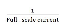
And the full-scale voltage reading and full-scale current (full-scale current resistance).
For example, if a meter has a full-scale current of 50μA and a resistance of 960Ω, the sensitivity could be calculated as:

The full-scale voltage reading would be calculated as:
- Full-scale voltage reading = full-scale current resistance
- Full-scale voltage reading = 50μA x 960Ω
- Full-scale voltage reading = 48mV
Ranges
The table below shows the figures for most meter movements in use today.
|
CURRENT TO DEFLECT FULL SCALE |
RESISTANCE |
SENSITIVITY |
VOLTAGE FULL SCALE |
|
1mA |
100Ω |
1 kΩ/VOLT |
.1V |
|
50µA |
960Ω |
20 kΩ/VOLT |
.048V |
|
5µA |
5750Ω |
30 kΩ/VOLT |
.029V |
Notice that the meter movements shown in the table above will indicate .029 volts to .1V at full scale, and the sensitivity ranges from 1000 ohms per volt to 200,000 ohms per volt. The higher sensitivity meters indicate smaller amounts of voltage. Since most voltage measurements involve voltage larger than .1 volt, a method must be used to extend the voltage reading.
The figure below illustrates the method of increasing the voltage range of a voltmeter.

In Figure (A), a voltmeter with a range of 10 volts and a resistance of 1 kilohm (R2) is connected in parallel to resistor R1.
The meter has .01 ampere of current (full-scale deflection) and indicates 10 volts.
Figure (B) shows that the voltage has been increased to 100 volts. This is more than the meter can measure.
A 9-kilohm resistor (R3) is connected in series with the meter (R2). The meter (R2) now has .01 ampere of current (full-scale deflection).
However, since R3 has increased the voltage capability of the meter, the meter indicates 100 volts. R3 has changed the range of the meter.

Voltmeters can be constructed with several ranges by the use of a switch and internal resistors.
The figure to the right shows a voltmeter with a meter movement of 100 ohms and one milliampere full-scale deflection with five voltage ranges through a switch. In this way, a voltmeter can be used to measure several different ranges of voltage.
The current through the meter movement is determined by the voltage being measured. If the voltage measured is higher than the range of the voltmeter, the excess current will flow through the meter movement, and the meter will be damaged. Therefore, you should always start with the highest range of a voltmeter and switch the ranges until a reading is obtained near the center of the scale.
The figure to the left illustrates these points.
In Figure (A), the meter is in the 1000-volt range. The pointer is barely above the 0 position. It is not possible to accurately read this voltage.
In Figure (B), the meter is switched to the 250-volt range. It is possible to approximate the voltage as 20 volts from the pointer position. Since this is well below the next range, the meter is switched, as in Figure (C).
With the meter in the 50-volt range, it is possible to read the voltage as 22 volts. Since this is more than the next range of the meter (10 volts), the meter would not be switched to the next (lower) scale.
Electrostatic Meter Movement
The final meter movement covered in this section is the Electrostatic Meter Movement. The other meter movements you have studied all react to current. The electrostatic meter movement reacts to voltage.
- The mechanism is based on the repulsion of like charges on the plates of a capacitor.
- The electrostatic meter movement is actually a large variable capacitor in which one set of plates is allowed to move.
- The movement of the plates is opposed by a spring attached to the plates.
- A pointer that indicates the value of the voltage is attached to these movable plates.
- As the voltage increases, the plates develop more torque.
- To develop sufficient torque, the plates must be large and closely spaced.
- A very high voltage is necessary to provide movement; therefore, electrostatic voltmeters are used only for high-voltage measurement.
Voltmeter Safety Precautions
Just as with ammeters, voltmeters require safety precautions to prevent injury to personnel and damage to the voltmeter or equipment.
The following is a list of the minimum safety precautions for using a voltmeter.
- Always connect voltmeters in parallel.
- Always start with the highest range of a voltmeter.
- Deenergize and discharge the circuit completely before connecting or disconnecting the voltmeter.
- In DC voltmeters, observe the proper circuit polarity to prevent damage to the meter.
- Never use a DC voltmeter to measure AC voltage.
- Observe the general safety precautions of electrical and electronic devices.
Ohmmeters and Meggers
The two instruments most commonly used to check the continuity (a complete circuit) or to measure the resistance of a circuit or circuit element are the ohmmeter and the megger (megohmmeter).
- The ohmmeter is widely used to measure resistance and check the continuity of electrical circuits and devices. Its range usually extends to only a few megohms.
- The megger is widely used for measuring insulation resistance, such as between a wire and the outer surface of the insulation and the insulation resistance of cables and insulators.
Ohmmeter
An ohmmeter is an electrical instrument that measures electrical resistance, the opposition to an electric current.
 Micro-ohmmeters (microhmmeter or micro ohmmeter) make low resistance measurements. Megohmmeters (aka megaohm meter or, in the case of a trademarked device, Megger) measure large values of resistance. The unit of measurement for resistance is ohms (Ω).
The first ohmmeters were based on a type of meter movement known as a ‘ratiometer’. These were similar to the galvanometer-type movement encountered in later instruments, but instead of hairsprings to supply a restoring force, they used conducting ‘ligaments’ instead. These provided no net rotational force to the movement. Also, the movement was wound with two coils. One was connected via a series resistor to the battery supply. The second was connected to the same battery supply via a second resistor, and the resistor was under test.
The indication on the meter was proportional to the ratio of the currents through the two coils. This ratio was determined by the magnitude of the resistor under test. The advantages of this arrangement were twofold.
- First, the indication of the resistance was completely independent of the battery voltage (as long as it actually produced some voltage), and no zero adjustments were required.
- Second, although the resistance scale was nonlinear, the scale remained correct over the full deflection range. By interchanging the two coils, a second range was provided. This scale was reversed compared to the first.
A feature of this type of instrument was that it would continue to indicate a random resistance value once the test leads were disconnected (the action of which disconnected the battery from the movement).
Ohmmeters of this type only measured resistance as they could not easily be incorporated into a multimeter design. Insulation testers that relied on a hand-cranked generator operated on the same principle. This ensured that the indication was wholly independent of the voltage actually produced.
Subsequent designs of ohmmeters provided a small battery to apply a voltage to resistance via a galvanometer to measure the current through the resistance. The scale of the galvanometer was marked in ohms because the fixed voltage from the battery ensured that as resistance decreased, the current through the meter would increase.
Ohmmeters form circuits by themselves; therefore, they cannot be used within an assembled circuit. This design is much simpler and cheaper than the former design and was simple to integrate into a multimeter design and consequently was by far the most common form of an analog ohmmeter.
This type of ohmmeter suffers two inherent disadvantages.
- First, the meter needs to be zeroed by shorting the measurement points together and performing an adjustment for zero ohms indication prior to each measurement. This is because as the battery voltage decreases with age, the series resistance in the meter needs to be reduced to maintain the zero indication at full deflection.
- Second, and consequent on the first, the actual deflection for any given resistor under test changes as the internal resistance is altered. It remains correct at the centre of the scale, which is why such ohmmeter designs always quote the accuracy “at centre scale only.”
A more accurate type of ohmmeter has an electronic circuit that passes a constant current (I) through the resistance,
and another circuit that measures the voltage (V) across the resistance.
According to the following equation, derived from Ohm’s Law, the value of the resistance (R) is given by:

For high-precision measurements, the above types of meters are inadequate. This is because the meter’s reading is the sum of the resistance of the measuring leads, the contact resistances, and the resistance being measured.
A precision ohmmeter has four terminals called Kelvin contacts to reduce this effect. Two terminals carry the current from the meter, while the other two allow the meter to measure the voltage across the resistor. With this type of meter, any voltage drop due to the resistance of the first pair of leads and their contact resistances is ignored by the meter.
This four-terminal measurement technique is called Kelvin sensing, after William Thomson, Lord Kelvin, who invented the Kelvin Bridge in 1861 to measure very low resistances. The Four-terminal sensing method can also be used to measure low resistances accurately. The ohmmeter consists of a DC ammeter with a few added features.
The added features are:
- A DC source of potential
- One or more resistors (one of which is variable).
- A simple ohmmeter circuit is shown in the figure below.
The ohmmeter’s pointer deflection is controlled by the amount of battery current passing through the moving coil. Before measuring the resistance of an unknown resistor or electrical circuit, the ohmmeter test leads are first shorted together, as shown in the figure below.
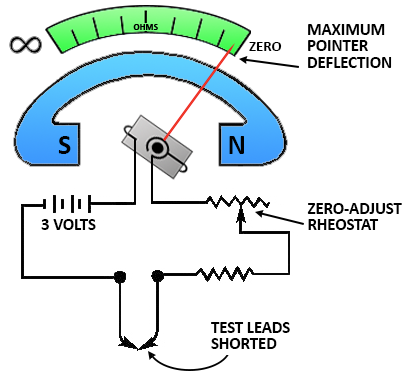 With the leads shorted, the meter is calibrated for proper operation on the selected range.
While the leads are shorted, the meter current is maximum, and the pointer deflects a maximum amount somewhere near the zero position on the ohms scale. Because of this current through the meter with the leads shorted, it is necessary to remove the test leads when you are finished using the ohmmeter. If the leads were left connected, they could come in contact with each other and discharge the ohmmeter battery.
When the variable resistor (rheostat) is adjusted properly, with the leads shorted, the meter pointer will rest exactly on the zero position.
This indicates zero resistance between the test leads, which, in fact, are shorted together.
The zero reading of a series-type ohmmeter is on the right-hand side of the scale, whereas the zero reading for an ammeter or a voltmeter is generally to the left-hand side of the scale. (There is another type of ohmmeter, which is discussed a little later on in this series.)
When the test leads of an ohmmeter are separated, the pointer of the meter will return to the left side of the scale. The interruption of current and the spring tension act on the movable coil assembly, moving the pointer to the left side (∞) of the scale.
Using The Ohmmeter
After the ohmmeter is adjusted for zero reading, it is ready to be connected to a circuit to measure resistance. A typical circuit and ohmmeter arrangement is shown in the figure below.
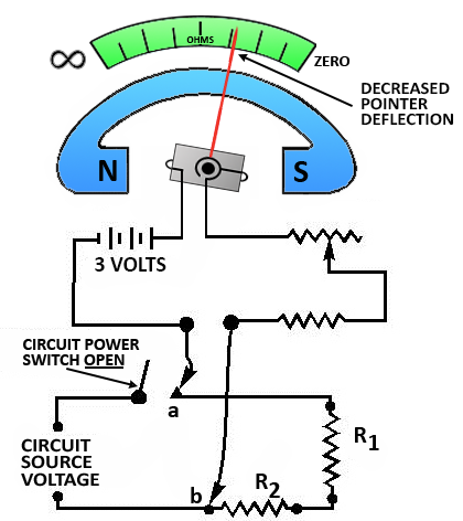 The power switch of the circuit to be measured should always be in the OFF position. This prevents the source voltage of the circuit from being applied across the meter, which could cause damage to the meter’s movement.
The ohmmeter test leads are connected in series with the circuit to be measured. This causes the current produced by the 3-volt battery of the meter to flow through the circuit being tested.
Assume the meter test leads are connected at points a and b. The amount of current that flows through the meter coil will depend on the total resistance of resistors R1 and R2 and the resistance of the meter.
Since the meter has been pre-adjusted (zeroed), the amount of coil movement now depends solely on the resistance of R1 and R2. The inclusion of R1 and R2 raises the total series resistance, decreasing the current and thus decreasing the pointer deflection. The pointer will now come to rest at a scale figure indicating the combined resistance of R1 and R2.
If R1 or R2, or both, were replaced with a resistor(s) having a larger value, the current flow in the moving coil of the meter would be decreased further. The deflection would also decrease further, and the scale indication would read a higher circuit resistance. The movement of the moving coil is proportional to the amount of current flow.
Ohmmeter Ranges
The amount of circuit resistance to be measured may vary over a wide range. In some cases, it may be only a few ohms; in others, it may be as great as 1,000,000 ohms (1 megohm). Scale multiplication features are used in most ohmmeters to enable the meter to indicate any value being measured with the least error.
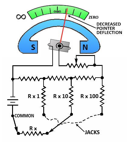
For example, a typical meter will have four test lead jacks-COMMON, R x 1, R x 10, and R x 100.
- The jack marked COMMON is connected internally through the battery to one side of the moving coil of the ohmmeter.
- The jacks marked R x 1, R x 10, and R x 100 are connected to three different-size resistors located within the ohmmeter. This is shown in the figure below.
 Some ohmmeters are equipped with a selector switch for selecting the multiplication scale desired, so only two test lead jacks are necessary.
The range to be used in measuring any particular unknown resistance (Rx in the figure to the right) depends on the approximate value of the unknown resistance. For instance, assume the ohmmeter is calibrated in divisions from 0 to 1,000.
- If Rx is greater than 1,000 ohms, and the R x 1 range is being used, the ohmmeter cannot measure it.
- This occurs because the combined series resistance of resistors R x 1 and Rx is too great to allow sufficient battery current to flow to deflect the pointer away from infinity (∞). (Infinity is a quantity larger than the largest quantity you can measure.)
- The test lead would have to be plugged into the next range, R x 10. With this done, assume the pointer deflects to indicate 375 ohms.
- This would indicate that Rx has 375 ohms x 10 or 3,750 ohms resistance.
- The change of range caused the deflection because resistor R x 10 has about 1/10 the resistance of resistor R x 1.
Thus, selecting the smaller series resistance permitted a battery current of a sufficient amount to cause a useful pointer deflection.
If the R x 100 range were used to measure the same 3,750-ohm resistor, the pointer would deflect still further to the 37.5-ohm position. This increased deflection would occur because resistor R x 100 has about 1/10 the resistance of resistor R x 10.
The foregoing circuit arrangement allows the same amount of current to flow through the meter’s moving coil, whether the meter measures 10,000 ohms on the R x 10 scale or 100,000 ohms on the R x 100 scale. It always takes the same amount of current to deflect the pointer to a certain position on the scale (midscale position, for example), regardless of the multiplication factor being used.
Since the multiplier resistors are of different values, it is necessary to always “zero” adjust the meter for each multiplication factor selected. You should select the multiplication factor (range) that will result in the pointer coming to rest as near as possible to the midpoint of the scale.
This enables you to read the resistance more accurately because the scale readings are more easily interpreted at or near the midpoint.
Shunt Ohmmeter
The ohmmeter described to this point is known as a series ohmmeter because the resistance to be measured is in series with the internal resistors and the meter movement of the ohmmeter.
Another type of ohmmeter is the Shunt Ohmmeter.
In the shunt ohmmeter, the resistance to be measured shunts (is in parallel with) the meter movement of the ohmmeter. The most obvious way to tell the difference between the series and shunt ohmmeters is by the scale of the meter.
The figure below shows the scale of a series ohmmeter and the scale of a shunt ohmmeter.

- Figure (A) is the scale of a series ohmmeter. Notice “0” is on the right and “∞” is on the left.
- Figure (B) is the scale of a shunt ohmmeter. If the shunt ohmmeter “∞” is on the right and “0” is on the left.
A shunt ohmmeter circuit is shown in the figure below.
R1 is a rheostat used to adjust the ∞ reading of the meter (full-scale deflection).
- R1, R2, R3, and R4 are used to provide the R x 1, R x 10, and R x 100 ranges.
- Points A and B represent the meter leads.
With no resistance connected between points A and B, the meter has full-scale current and indicates ∞.
If resistance is connected between points A and B, it shunts some of the current from the meter movement, and the meter movement reacts to this lower current. Since the scale of the meter is marked in ohms, the resistance of the shunting resistor (between points A and B) is indicated.
Notice that the switch has an OFF position and positions for R x 1, R x 10, and R x 100. This is provided to stop the current flow and prevent the battery from being discharged while the meter is not being used.
The shunt ohmmeter is connected to the circuit to be measured in the same way the series ohmmeter is connected. The only difference is that on the shunt ohmmeter, the ∞ reading is adjusted, while on the series ohmmeter, the 0 reading is adjusted.
Shunt ohmmeters are not commonly used because they are generally limited to measuring resistances from 5 ohms to 400 ohms. If you use a shunt ohmmeter, be certain to switch it to the OFF position when you are finished using it.
Ohmmeter Safety Precautions
The following safety precautions and operating procedures for ohmmeters are the minimum necessary to prevent injury and damage.
- Be certain the circuit is de-energized and discharged before connecting an ohmmeter.
- Do not apply power to a circuit while measuring resistance.
- When you are finished using an ohmmeter, switch it to the OFF position if one is provided and remove the leads from the meter.
- Always adjust the ohmmeter for 0 (or ∞ in shunt ohmmeter) after you change ranges before making the resistance measurement.
Megohmmeter
An ordinary ohmmeter cannot be used for measuring the resistance of multimillions of ohms, such as in conductor insulation. To adequately test for insulation breakdown, it is necessary to use a much higher potential than is furnished by the battery of an ohmmeter. This potential is placed between the conductor and the outside surface of the insulation.
 An instrument called a Megohmmeter (Megger) is used for these tests. A Megohmmeter (sometimes referred to as a megger) is a special type of ohmmeter used to measure the electrical resistance of insulators.
Insulating components, for example, cable jackets, must be tested for their insulation strength at the time of commissioning and as part of the maintenance of high-voltage electrical equipment and installations.
For this purpose, Megohmmeters, which can provide high DC voltages (typically in ranges from 500V to 2kV) at specified current capacity, are used. Acceptable insulator resistance values are typically 1 to 10 megohms, depending on the standards referenced. The range of a megger may extend to more than 1,000 megohms.
The megger is a portable instrument consisting of two primary elements:
- a DC generator that supplies the high voltage for making the measurement and
- the instrument portion, which indicates the value of the resistance being measured.
The instrument portion is of the opposed-coil type, as shown in the figure below.
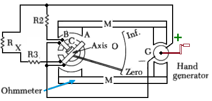
- Coils A and B are mounted on the movable member C with a fixed relationship to each other and are free to turn as a unit in a magnetic field.
- Coil B tends to move the pointer counterclockwise, and Coil A tends to move the pointer clockwise.
- Coil A is connected in series with R3, and the unknown resistance, Rx, is measured.
- The combination of coil, R3, and Rx forms a direct series path between the positive (+) and negative (–) brushes of the DC generator.
- Coil B is connected in series with R2, and this combination is also connected across the generator.
There are no restraining springs on the movable member of the instrument portion of the megger. Therefore, when the generator is not operated, the pointer floats freely and may rest at any scale position.
The guard ring intercepts leakage current. Any leakage currents intercepted are shunted to the negative side of the generator. They do not flow through coil A; therefore, they do not affect the meter reading.
- If the test leads are open-circuited, no current flows in coil A. However, current flows internally through coil B and deflects the pointer to infinity, which indicates a resistance too large to measure.
- When a resistance such as Rx is connected between the test leads, current also flows in coil A, tending to move the pointer clockwise.
- At the same time, coil B still tends to move the pointer counterclockwise.
Therefore, the moving element, composed of both coils and the pointer, rests in a position where the two forces are balanced. This position depends upon the value of the external resistance, which controls the relative amount of current in coil A.
Because changes in voltage affect both coil a and coil b in the same proportion, the position of the moving system is independent of the voltage. If the test leads are short-circuited, the pointer rests at zero because the current in coil a is relatively large. The instrument is not damaged under these circumstances because R3 limits the current.
When extremely high resistances, for example, 10,000 megohms or more-are to be measured, a high voltage is needed to cause sufficient current flow to actuate the meter movement. For extended ranges, a 1,000-volt generator is available.
When a megger is used, the generator voltage is present on the test leads. This voltage could be hazardous to you or to the equipment you are checking.
Therefore, never touch the test leads while the megger is being used, and isolate the item you are checking from the equipment before using the megger.
Using the Megger
- To use a megger to check wiring insulation, connect one test lead to the insulation and the other test lead to the conductor after isolating the wiring from the equipment.
- Normal insulations should read infinity.
- Any small resistance reading indicates the insulation is breaking down.
Megger Safety Precautions
When you use a megger, you could be injured or damage the equipment you are working on if the following minimum safety precautions are not observed.
- Use meggers on high-resistance measurements only (such as insulation measurements or to check two separate conductors on a cable).
- Never touch the test leads while the handle is being cranked.
- Deenergize and discharge the circuit completely before connecting a megger.
- If possible, disconnect the item being checked from other circuitry before using a merger.
Multimeter
A Multimeter is the most common measuring device used in the electrical field. The name multimeter comes from Multiple Meter, and that is exactly what a multimeter is. It is a DC ammeter, a DC voltmeter, an AC voltmeter, and an ohmmeter, all in one package.
 A multimeter or a multitester, also known as a VOM (Volt-Ohm meter), is an electronic measuring instrument that combines several measurement functions in one unit. A typical multimeter would include basic features such as the ability to measure voltage, current, and resistance.
Analog multimeters use a microammeter whose pointer moves over a scale calibrated for all the different measurements that can be made.
Digital multimeters (DMM, DVOM) display the measured value in numerals and may also display a bar of a length proportional to the quantity being measured.
Digital multimeters are now far more common than analog ones, but analog multimeters are still preferable in some cases, for example, when monitoring a rapidly varying value.
 A multimeter can be a hand-held device useful for basic fault finding and field service work or a bench instrument that can measure very high accuracy. They can be used to troubleshoot electrical problems in a wide array of industrial and household devices, such as electronic equipment, motor controls, domestic appliances, power supplies, and wiring systems.
Multimeters are available in a wide range of features and prices. Cheap multimeters cost less than $10, while top-of-the-line multimeters cost more than $5,000.
History
Multimeters were invented in the early 1920s as radio receivers and other vacuum tube electronic devices became more common.
The invention of the first multimeter is attributed to British Post Office engineer Donald Macadie, who became dissatisfied with having to carry many separate instruments required for the maintenance of the telecommunications circuits.
Macadie invented an instrument that could measure amperes (amps), volts, and ohms, so the multifunctional meter was then named Avometer. The meter comprised a moving coil meter, voltage and precision resistors, and switches and sockets to select the range.
Macadie took his idea to the Automatic Coil Winder and Electrical Equipment Company (ACWEEC, founded in ~1923). The first AVO was put on sale in 1923, and many of its features remained almost unaltered through to the last Model 8.
Pocket watch style meters were in widespread use in the 1920s at a much lower cost than Avometers.
The metal case was normally connected to the negative connection, an arrangement that caused numerous electric shocks. The technical specifications of these devices were often crude. For example, the one illustrated has a resistance of just 33 ohms per volt, a non-linear scale, and no zero adjustment.
Any meter will load the circuit under test to some extent. For example, a microammeter with a full-scale current of 50 microamps, the highest sensitivity commonly available, must draw at least 50 microamps from the circuit under test to deflect fully.
This may load a high-impedance circuit so much as to affect the circuit and give a low reading.
Vacuum Tube Voltmeters or valve voltmeters (VTVM, VVM) were used for voltage measurements in electronic circuits where high impedance was necessary.
 The VTVM had a fixed input impedance of typically one megohm or more, usually through the use of a cathode follower input circuit, and thus did not significantly load the circuit being tested. Voltmeters were used before the introduction of digital electronic high-impedance analog transistors and field-effect transistors (FETs).
Modern digital meters and some modern analog meters use electronic input circuitry to achieve high-input impedance—their voltage ranges are functionally equivalent to VTVMs.
Additional scales such as decibels and measurement functions such as capacitance, transistor gain, frequency, duty cycle, display hold, and buzzers, which sound when the measured resistance is small, have been included on many multimeters.
While multimeters may be supplemented by more specialized equipment in a technician’s toolkit, some multimeters include additional functions for specialized applications (temperature with a thermocouple probe, inductance, connectivity to a computer, speaking measured value, etc.).
Operation
A multimeter is a combination of a multi-range DC voltmeter, multi-range AC voltmeter, multi-range ammeter, and mult-irange ohmmeter.

An un-amplified analog multimeter combines a meter movement, range resistors, and switches. For an analog meter movement, DC voltage is measured with a series resistor connected between the meter movement and the circuit under test. A set of switches allows greater resistance to be inserted for higher voltage ranges.
The product of the basic full-scale deflection current of the movement and the sum of the series resistance and the movement’s own resistance gives the full-scale voltage of the range. For example, a meter movement that required one milliampere for full-scale deflection, with an internal resistance of 500 ohms, would, on a 10-volt range of the multimeter, have 9,500 ohms of series resistance.
For analog current ranges, low-resistance shunts are connected in parallel with the meter movement to divert most of the current around the coil. Again, for a hypothetical one mA, 500-ohm movement on a 1 Ampere range, the shunt resistance would be just over 0.5 ohms. Moving coil instruments respond only to the average value of the current through them.
To measure alternating current, a rectifier diode is inserted in the circuit so that the average value of current is non-zero. Since the rectified average value and the root-mean-square value of a waveform need not be the same, simple rectifier-type circuits may only be accurate for sinusoidal waveforms.
Other wave shapes require a different calibration factor to relate RMS and average values. Since practical rectifiers have non-zero voltage drops, accuracy and sensitivity are poor at low values.
To measure resistance, a small battery within the instrument passes a current through the device under test and the meter coil. Since the current available depends on the battery’s state of charge, a multimeter usually has an adjustment for the ohms scale to zero it.
In the usual circuit found in analog multimeters, the meter deflection is inversely proportional to the resistance, so full-scale is 0 ohms and high resistance corresponds to smaller deflections.
- The ohms scale is compressed, so the resolution is better at lower resistance values.
- Amplified instruments simplify the design of the series and shunt resistor networks.
- The internal resistance of the coil is decoupled from the selection of the series and shunt range resistors; the series network becomes a voltage divider.
Where AC measurements are required, the rectifier can be placed after the amplifier stage, improving precision at low range.
Digital instruments, which necessarily incorporate amplifiers, use the same principles as analog instruments for range resistors.
For resistance measurements, a small constant current is usually passed through the device under test, and the digital multimeter reads the resultant voltage drop; this eliminates the scale compression found in analog meters but requires a source of significant current.
An auto-ranging digital multimeter can automatically adjust the scaling network so that the measurement uses the full precision of the A/D converter.
In all types of multimeters, the quality of the switching elements is critical to stable and accurate measurements. The stability of the resistors is a limiting factor in the long-term accuracy and precision of the instrument.
Quantities Measured
Contemporary multimeters can measure many quantities. The common ones are:
- Voltage, AC, and DC, in volts.
- Current, AC, and DC, in amperes.
The frequency range for which AC measurements are accurate must be specified.
- Resistance in ohms.
Additionally, some multimeters measure:
- Capacitance in farads.
- Conductance in Siemens.
- Decibels
- Duty cycle as a percentage.
- Frequency in hertz.
- Inductance in henrys.
- The temperature in degrees Celsius or Fahrenheit, with an appropriate temperature test probe, often a thermocouple.
- Digital multimeters may also include circuits for:
- Continuity tester: sounds when a circuit conducts.
- Diodes (measuring forward drop of diode junctions) and transistors (measuring current gain and other parameters)
- Battery checking for simple 1.5-volt and 9-volt batteries. This is a current-loaded voltage scale that simulates in-use voltage measurement.
Various sensors can be attached to multimeters to take measurements, such as:
- Light level
- Acidity/Alkalinity(pH)
- Wind speed
- Relative humidity
Resolution and Accuracy
A multimeter’s resolution is the smallest part of the scale that can be shown. The resolution is scale-dependent.
On some digital multimeters, it can be configured, with higher resolution measurements taking longer to complete. For example, a multimeter that has a 1mV resolution on a 10V scale can show changes in measurements in 1mV increments.
- Absolute accuracy is the error of the measurement compared to a perfect measurement.
- Relative accuracy is the error of the measurement compared to the device used to calibrate the multimeter.
Most multimeter datasheets provide relative accuracy.
To compute the absolute accuracy from the relative accuracy of a multimeter, add the absolute accuracy of the device used to calibrate the multimeter to the relative accuracy of the multimeter.
Digital: a multimeter’s resolution is often specified in the number of decimal digits resolved and displayed. If the most significant digit cannot take all values from 0 to 9, it is often termed a fractional digit. For example, a multimeter that can read up to 19999 (plus an embedded decimal point) is said to read 4½ digits.
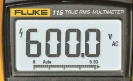
By convention, if the most significant digit can be either 0 or 1, it is termed a half-digit; if it can take higher values without reaching 9 (often 3 or 5), it may be called three-quarters of a digit.
A 5½ digit multimeter would display one “half digit” that could only display 0 or 1, followed by five digits, taking all values from 0 to 9. Such a meter could show positive or negative values from 0 to 199,999. Depending on the manufacturer, a 3¾ digit meter can display a quantity from 0 to 3,999 or 5,999.
While a digital display can easily be extended in precision, the extra digits are of no value if not accompanied by care in the design and calibration of the analog portions of the multimeter.
Meaningful high-resolution measurements require a good understanding of the instrument specifications, good control of the measurement conditions, and traceability of the calibration of the instrument. However, even if its resolution exceeds the accuracy, a meter can be useful for comparing measurements.
For example, a meter reading of 5½ stable digits may indicate that one nominally 100,000-ohm resistor is about 7 ohms greater than another, although the error of each measurement is 0.2% of reading plus 0.05% of the full-scale value.
Specifying “display counts” is another way to specify the resolution. Display counts give the largest number, or the largest number plus one (so the count number looks nicer) the multimeter’s display can show, ignoring a decimal separator.
For example, a 5½ digit multimeter can also be specified as a 199999 display count or 200000 display count multimeter. Often, the display count is just called the count in multimeter specifications.
Analog: The resolution of analog multimeters is limited by the width of the scale pointer, parallax, vibration of the pointer, the accuracy of printing of scales, zero calibration, number of ranges, and errors due to non-horizontal use of the mechanical display.

The accuracy of readings obtained is also often compromised by miscounting division markings, errors in mental arithmetic, parallax observation errors, and less-than-perfect eyesight.
Mirrored scales and larger meter movements are used to improve resolution; two and a half to three digits equivalent resolution is usual (and is usually adequate for the limited precision needed for most measurements).
Resistance measurements, in particular, are of low precision due to the typical resistance measurement circuit, which compresses the scale at higher resistance values. Inexpensive analog meters may have only a single resistance scale, seriously restricting the range of precise measurements.
Typically, an analog meter will have a panel adjustment to set the zero-ohms calibration of the meter to compensate for the varying voltage of the meter battery.
Accuracy
- Digital multimeters generally take measurements with accuracy superior to their analog counterparts.
- Standard analog multimeters typically measure with ±3% accuracy, though instruments of higher accuracy are made.
- Standard portable digital multimeters are specified to have an accuracy of typically 0.5% on the DC voltage ranges.
- Mainstream bench-top multimeters are available with a specified accuracy of better than ±0.01%. Laboratory-grade instruments can have accuracies of a few parts per million.
Accuracy figures need to be interpreted with care. The accuracy of an analog instrument usually refers to full-scale deflection; a measurement of 30V on the 100V scale of a 3% meter is subject to an error of 3V, 10% of the reading.
Digital meters usually specify accuracy as a percentage of reading plus a percentage of full-scale value, sometimes expressed in counts rather than percentage terms. Quoted accuracy is specified as being that of the lower millivolt (mV) DC range and is known as the “basic DC volts accuracy” figure.
Higher DC voltage ranges, current, resistance, AC, and other ranges will usually have lower accuracy than the basic DC volts figure. AC measurements only meet specified accuracy within a specified range of frequencies.
Manufacturers can provide calibration services so that new meters may be purchased with a certificate of calibration indicating the meter has been adjusted to standards traceable to, for example, the US National Institute of Standards and Technology (NIST) or other national standards organization.
Test equipment tends to drift out of calibration over time, and the specified accuracy cannot be relied upon indefinitely. Manufacturers and third parties provide calibration services for more expensive equipment so that older equipment may be recalibrated and recertified. The cost of such services is disproportionate for inexpensive equipment; however, extreme accuracy is not required for most routine testing.
Multimeters used for critical measurements may be part of a metrology program to ensure calibration. A multimeter can be assumed to be “average responding” to AC waveforms unless stated as being a “True RMS” type.
An average responding multimeter will only meet its specified accuracy on AC volts and amps for purely sinusoidal waveforms. A True RMS responding multimeter, on the other hand, will meet its specified accuracy on AC volts and current with any waveform type up to a specified crest factor.
A meter’s AC voltage and current accuracy may have different specifications for different ranges of frequency.
Sensitivity And Input Impedance
When used for measuring voltage, the input impedance of the multimeter must be very high compared to the impedance of the circuit being measured; otherwise, circuit operation may be changed, and the reading will also be inaccurate.
Meters with electronic amplifiers (all digital multimeters and some analog meters) have a fixed input impedance that is high enough not to disturb most circuits. This is often either one or ten megohms; the standardization of the input resistance allows the use of external high-resistance probes, which form a voltage divider with the input resistance to extend the voltage range up to tens of thousands of volts.
High-end multimeters generally provide an input impedance >10 Gigaohms for ranges less than or equal to 10V. Some high-end multimeters provide >10 Gigaohms of impedance to ranges greater than 10V.
Most analog multimeters of the moving-pointer type are un-buffered and draw current from the circuit under test to deflect the meter pointer. The impedance of the meter varies depending on the basic sensitivity of the meter movement and the range that is selected. For example, a meter with a typical 20,000 ohms/volt sensitivity will have an input resistance of two million ohms in the 100-volt range (100 V * 20,000 ohms/volt = 2,000,000 ohms).
On every range, at a full-scale voltage of the range, the full current required to deflect the meter movement is taken from the circuit under test.
Lower sensitivity meter movements are acceptable for testing in circuits where source impedances are low compared to the meter impedance, for example, power circuits; these meters are more rugged mechanically.
Some measurements in signal circuits require higher sensitivity movements so as not to load the circuit under test with the meter impedance.
The sensitivity should not be confused with the resolution of a meter, which is defined as the lowest signal change (voltage, current, resistance…) that can change the observed reading.
For general-purpose digital multimeters, the lowest voltage range is typically several hundred millivolts AC or DC, but the lowest current range may be several hundred microamperes, although instruments with greater current sensitivity are available.
Multimeters designed for (main) “electrical” use instead of general electronics engineering use will typically forego the microamp’s current ranges. Measurement of low resistance requires lead resistance (measured by touching the test probes together) to be subtracted for best accuracy. This can be done with the “delta,” “Zero,” or “null” feature of many digital multimeters.
The upper end of multimeter measurement ranges varies considerably; measurements over perhaps 600 volts, 10 amperes, or 100 megohms may require a specialized test instrument.
Burden Voltage
Any ammeter, including a multimeter in a current range, has a certain resistance. Most multimeters inherently measure voltage and pass a current to be measured through a shunt resistance, measuring the voltage developed across it.
The voltage drop is known as the burden voltage, specified in volts per ampere. The value can change depending on the range the meter selects since different ranges usually use different shunt resistors. The burden voltage can be significant in very low-voltage circuit areas.
To check for its effect on accuracy and on external circuit operation, the meter can be switched to different ranges; the current reading should be the same, and circuit operation should not be affected if burden voltage is not a problem.
If this voltage is significant, it can be reduced (also reducing the inherent accuracy and precision of the measurement) by using a higher current range.
Alternating Current Sensing
Since the basic indicator system in an analog or digital meter responds to DC only, a multimeter includes an AC-to-DC conversion circuit for alternating current measurements.
Basic meters utilize a rectifier circuit to measure the average or peak absolute value of the voltage but are calibrated to show the calculated root mean square (RMS) value for a sinusoidal waveform; this will give correct readings for alternating current as used in power distribution.
User guides for some such meters give correction factors for some simple non-sinusoidal waveforms to allow the correct root mean square(RMS) equivalent value to be calculated.
More expensive multimeters include an AC-to-DC converter that measures the true RMS value of the waveform within certain limits; the user manual for the meter may indicate the limits of the crest factor and frequency for which the meter calibration is valid.
RMS sensing is necessary for measurements of non-sinusoidal periodic waveforms, such as those found in audio signals and variable-frequency drives.
Digital Multimeters (DMM OR DVOM)

Modern multimeters are often digital due to their accuracy, durability, and extra features. In a digital multimeter, the signal under test is converted to a voltage, and an amplifier with electronically controlled gain preconditions the signal. A digital multimeter displays the quantity measured as a number, which eliminates parallax errors.
Modern digital multimeters may have an embedded computer, which provides a wealth of convenience features. Measurement enhancements available include:
- Auto-ranging selects the correct range for the quantity under test to show the most significant digits. For example, a four-digit multimeter would automatically select an appropriate range to display 1.234 instead of 0.012 or overloading.
Auto-ranging meters usually include a facility to hold the meter to a particular range because a measurement that causes frequent range changes can be distracting to the user.
Other factors being equal, an auto-ranging meter will have more circuitry than an equivalent non-auto-ranging meter, which will be more costly but more convenient to use.
- Auto-polarity for direct-current readings shows if the applied voltage is positive (agrees with meter lead labels) or negative (opposite polarity to meter leads).
- Sample and hold will latch the most recent reading for examination after the instrument is removed from the circuit under test.
- Current-limited tests for voltage drop across semiconductor junctions. While not a replacement for a transistor tester, this facilitates testing diodes and a variety of transistor types.
- A graphic representation of the quantity under test, as a bar graph. This makes go/no-go testing easy and also allows spotting of fast-moving trends.
- A low-bandwidth oscilloscope.
- Automotive circuit testers, including tests for automotive timing and dwell signals.
- Simple data acquisition features to record maximum and minimum readings over a given period or take several samples at fixed intervals.
- Integration with tweezers for surface-mount technology.
- A combined LCR meter for small-size SMD and through-hole components.
Modern meters may be interfaced with a personal computer by IrDA links, RS-232 connections, USB, or an instrument bus such as IEEE-488. The interface allows the computer to record measurements as they are made. Some DMMs can store measurements and upload them to a computer. The first digital multimeter was manufactured in 1955 by Non-Linear Systems.
Analog Multimeters
 A multimeter may be implemented with a galvanometer meter movement or, less often, with a bar graph or simulated pointer such as an LCD or vacuum fluorescent display.
Analog multimeters are common; a quality analog instrument will cost about the same as a DMM.
Analog multimeters have the precision and reading accuracy limitations described above and so are not built to provide the same accuracy as digital instruments.
Analog meters are able to display a changing reading in real-time, whereas digital meters present such data in a manner that’s either hard to follow or, more often, incomprehensible.
Also, an intelligible digital display follows changes in a circuit far more slowly than an analog movement, so it often fails to clearly show what’s going on.
Some digital multimeters include a fast-responding bar graph display for this purpose, though the resolution of these is usually low.
Analog meters are also useful in situations where it is necessary to pay attention to something other than the meter, and the swing of the pointer can be noticed without looking directly at it. This can happen when accessing awkward locations or working on cramped live circuitry.
Analog meter movements are inherently more fragile physically and electrically than digital meters. Many analog meters have been instantly broken by connecting to the wrong point in a circuit while on the wrong range or by dropping onto the floor.
Many analog multimeters feature a switch position marked “transit” to protect the meter’s movement during transportation. This feature works by placing a low resistance across the movement winding, resulting in dynamic braking.
Sensitive meter movements may be protected in the same manner by connecting a shorting or jumper wire between the terminals when not in use.
Meters that feature a shunt across the winding, such as an ammeter, may not require further resistance to arrest uncontrolled movements of the meter needle because of the low resistance of the shunt.
The ARRL handbook also says that analog multimeters, with no electronic circuitry, are less susceptible to radio frequency interference.
The meter movement in a moving pointer analog multimeter is practically always a moving-coil galvanometer of the d’Arsonval type, using either jeweled pivots or taut bands to support the moving coil.
In a basic analog multimeter, the current to deflect the coil and pointer is drawn from the circuit being measured; it is usually an advantage to minimize the current drawn from the circuit.
The sensitivity of an analog multimeter is given in units of ohms per volt.
For example, a low-cost multimeter with a sensitivity of 1000 ohms per volt would draw one milliampere from a circuit at full-scale deflection.
More expensive (and mechanically more delicate) multimeters typically have sensitivities of 20,000 ohms per volt and sometimes higher, with a 50,000 ohms per volt meter (drawing 20 microamperes at full scale) being about the upper limit for a portable, general-purpose, non-amplified analog multimeter.
To avoid loading the measured circuit by the current drawn by the meter movement, some analog multimeters use an amplifier inserted between the measured circuit and the meter movement.
While this increased the meter’s expense and complexity, by using vacuum tubes or field-effect transistors, the input resistance can be made very high and independent of the current required to operate the meter movement coil.
Such amplified multimeters are called VTVMs (vacuum tube voltmeters), TVMs (transistor voltmeters), FET-VOMs, and similar names.
Probes

A multimeter can utilize a variety of test probes to connect to the circuit or device under test. Crocodile clips, retractable hook clips, and pointed probes are the three most common attachments. Tweezer probes are used for closely spaced test points, as in surface-mount devices. The connectors are attached to flexible, thickly insulated leads that are terminated with connectors appropriate for the meter.

Probes are connected to portable meters typically by shrouded or recessed banana jacks, while benchtop meters may use banana jacks or BNC connectors. 2mm plugs and binding posts have also been used at times but are less common today.
Clamp meters clamp around a conductor carrying a current to measure without connecting the meter in series with the circuit or making metallic contact at all. Types to measure AC current use the transformer principle; clamp-on meters to measure small current or direct current require more complicated sensors.
Safety
All but the most inexpensive multimeters include a fuse or two fuses, which sometimes prevent damage to the multimeter from a current overload on the highest current range. A common error when operating a multimeter is to set the meter to measure resistance or current and then connect it directly to a low-impedance voltage source.
 Such errors often quickly destroy unused meters; fused meters often survive. Fuses used in meters will carry the maximum measuring current of the instrument but are intended to clear if operator error exposes the meter to a low-impedance fault.
Meters with unsafe fusing are not uncommon; this situation has led to the creation of the IEC61010 categories.
Digital meters are rated into four categories based on their intended application, as set forth by IEC 61010 -1 and echoed by country and regional standards groups such as the CEN EN61010 standard.
- Category I: used where equipment is not directly connected to the mains.
- Category II: used on single-phase mains final sub-circuits.
- Category III: used on permanently installed loads such as distribution panels, motors, and 3-phase appliance outlets.
- Category IV: used on locations where fault current levels can be very high, such as supply service entrances, main panels, supply meters, and primary over-voltage protection equipment.
Each category also specifies maximum transient voltages for selected measuring ranges in the meter. Category-rated meters also feature protections from over-current faults. Optical isolation may protect attached equipment against high voltage in the measured circuit on meters that allow interfacing with computers.
High-quality multimeters designed to meet CAT II and above ratings will include High Rupture Capacity ceramic fuses typically rated at more than 20kA breaking capacity. They will also include high energy overvoltage MOV (Metal Oxide Varistor) protection and circuit overcurrent protection in the form of a Polyswitch.
DMM Alternatives
A general-purpose electronics DMM is generally considered adequate for measurements at signal levels greater than one millivolt or one microampere or below about 100 megohms—levels far from the theoretical limits of sensitivity.
Other instruments—essentially similar but with higher sensitivity—are used for accurate measurements of very small or very large quantities. These include nanovoltmeters, electrometers (for very low currents and voltages with very high source resistance, such as one teraohm), and picoammeters. These measurements are limited by available technology and, ultimately, by inherent thermal noise.
Power Supply
Analog meters can measure voltage and current using power from the test circuit but require internal power for resistance testing; electronic meters always require an internal power supply.
Hand-held meters use batteries, while bench meters usually use mains power, allowing the meter to test devices not connected to a circuit. Such testing requires that the component be isolated from the circuit as otherwise, other current paths will most likely distort measurements.
Meters intended for testing in hazardous locations or for use on blasting circuits may require the use of a manufacturer-specified battery to maintain their safety rating.
Parallax Error When Reading Analog Meters
Most analog multimeters (and some other meters) have a mirror built into the scale. The figure below shows the arrangement of the scale and mirror.

The mirror’s purpose on the meter scale is to aid in reducing Parallax Error. The figure below will help you understand the idea of parallax.
 Figure (A) shows a section of a barbed wire fence, as you would see from one side of the fence.
Figure (B) shows the fence as it would appear if you were to look down the line of fence posts and were directly in line with the posts. You see only one post because the other posts, being in line, are hidden behind the post you can see.
Figure (C) shows how the fence would appear if you moved to the right of the line of posts. Now, the fence posts appear to the right of the post closest to you.
Figure (D) shows the line of fence posts as you would see them if you moved to the left of the front post.
This apparent change in the position of the fence posts is called Parallax.
Parallax can be a problem when you are reading a meter. Since the pointer is slightly above the scale (to allow the pointer to move freely), you must look straight at the pointer to have a correct meter reading.
In other words, you must be in line with the pointer and the scale. The figure below shows the effect of parallax error.

Figure (A) shows a meter viewed correctly. The meter reading is (5) units.
Figure (B) shows the same meter as it would appear if you were to look at it from the right. The correct reading (5) appears to the right of the pointer because of parallax.
The mirror on the scale of a meter, shown in the figure below, helps eliminate parallax errors. If there is any parallax, you will be able to see the image of the pointer in the mirror.
If you are looking at the meter correctly (no parallax error), you will not be able to see the image of the pointer in the mirror because the image will be directly behind the pointer.
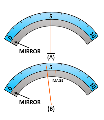
The Figure to the left shows how a mirror added to the meter in the figure above shows a parallax error.
Figure (A) is a meter with an indication of 5 units. There is no parallax error in this reading, and no image of the pointer is seen in the mirror.
Figure (B) shows the same meter as viewed from the right. The parallax error is shown, and the image of the pointer is shown in the mirror.
Multimeter Safety Precautions
As with other meters, the incorrect use of a multimeter could cause injury or damage. The following safety precautions are the minimum for using a multimeter.
- Deenergize and discharge the circuit completely before connecting or disconnecting a multimeter.
- Never apply power to the circuit while measuring resistance with a multimeter.
- Connect the multimeter in series with the circuit for current measurements and in parallel for voltage measurements.
- Be certain the multimeter is switched to AC before attempting to measure AC circuits.
- Observe proper DC polarity when measuring DC.
- When you are finished with a multimeter, switch it to the OFF position, if available.
Switch the multimeter to the highest AC voltage position if there is no OFF position.
- Always start with the highest voltage or current range.
- Select a final range that allows a reading near the middle of the scale.
- Adjust the “0 ohms” reading after changing resistance ranges and before making a resistance measurement.
- Be certain to read AC measurements on the AC scale of a multimeter.
- Observe the general safety precautions for electrical and electronic devices.
Other Meters
In addition to the ammeter, voltmeter, ohmmeter, and multimeter, you will probably use many other types of measuring devices. Some of those measuring devices (test equipment) are discussed below.
The following brief discussion of a few additional meters will introduce you to some of the common measuring devices you will use in working on electrical and electronic circuits.
Wattmeter

The wattmeter measures the electric power (or the supply rate of electrical energy) in watts of any given circuit.
Electromagnetic wattmeters are used for the measurement of utility frequency and audio frequency power; other types are required for radio frequency measurements.
Electrodynamic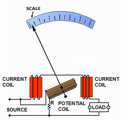
The traditional analog wattmeter is an electrodynamic instrument. The device consists of a pair of fixed coils, known as the current coils, and a movable coil, known as the potential coil. The current coils are connected in series with the circuit, while the potential coil is connected in parallel.
Also, on analog wattmeters, the potential coil carries a needle that moves over a scale to indicate the measurement. A current flowing through the current coil generates an electromagnetic field around the coil.
The strength of this field is proportional to the line current and in phase with it. As a general rule, the potential coil has a high-value resistor connected in series to reduce the current that flows through it.
The result of this arrangement is that on a DC circuit, the deflection of the needle is proportional to both the current and the voltage, thus conforming to the equation W=VA or P=VI.
Current and voltage may not be in phase for AC power owing to the delaying effects of circuit inductance or capacitance. On an AC circuit, the deflection is proportional to the average instantaneous product of voltage and current, thus measuring true power, P=VI cos φ.
Here, cosφ represents the power factor showing that the power transmitted may be less than the apparent power obtained by multiplying the voltmeter readings and ammeter in the same circuit.
The two circuits of a wattmeter can be damaged by excessive current. The ammeter and voltmeter are both vulnerable to overheating — in case of an overload, their pointers will be driven off the scale — but in the wattmeter, either or even both the current and potential circuits can overheat without the pointer approaching the end of the scale.
This is because the position of the pointer depends on the power factor, voltage, and current. Thus, a circuit with a low power factor will give a low reading on the wattmeter, even when both of its circuits are loaded to the maximum safety limit. Therefore, a wattmeter is rated not only in watts but also in volts and amperes.
A typical wattmeter in educational labs has two voltage coils (pressure coils) and a current coil. We can connect the two pressure coils in series or parallel to each other to change the ranges of the wattmeter.
Another feature is that the pressure coil can be tapped to change the meter’s range. If the pressure coil has a range of 300 volts, half of it can be used so that the range becomes 150 Volts.
Electrodynamometer
An early current meter was the electrodynamometer.
Used in the early 20th century, the Siemens electrodynamometer, for example, is a form of an electrodynamic ammeter, which has a fixed coil that is surrounded by another, having its axis at right angles to that of the fixed coil.
A number of silk fibers suspend this second coil, and to the coil is also attached a spiral spring, the other end of which is fastened to a torsion head. If the torsion head is twisted, the suspended coil experiences a torque and is displaced through an angle equal to that of the torsion head.
The current can be passed into and out of the movable coil by permitting the ends of the coil to dip into two mercury cups.
If a current is passed through the fixed coil and movable coil in series with one another, the movable coil tends to displace itself so as to bring the axes of the coils, which are normally at right angles, more into the same direction.
This tendency can be resisted by giving a twist to the torsion head and applying a restoring torque to the movable coil through the spring, which opposes the torque due to the dynamic action of the currents.
If the torsion head is provided with an index needle and the movable coil is provided with an indicating point, it is possible to measure the torsional angle through which the head must be twisted to bring the movable coil back to its zero position.
In these circumstances, the torsional angle becomes a measure of the torque and, therefore, of the product of the strengths of the currents in the two coils, that is to say, of the square of the strength of the current passing through the two coils if they are joined up in series.
Therefore, The instrument can be calibrated by passing through known continuous currents, and it becomes available for use with continuous or alternating currents.
The instrument can be provided with a calibration curve or table showing the current corresponding to each angular displacement of the torsion head.
Electronic Wattmeter
Electronic wattmeters are used for direct, small, or power measurements at frequencies beyond the range of electrodynamometer-type instruments, such as a Digital Wattmeter.
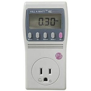
A modern digital electronic wattmeter/energy meter samples the voltage and current thousands of times a second.
For each sample, the voltage is multiplied by the current at the same instant; the average over at least one cycle is the real power. The power factor is the real power divided by the apparent volt-amperes (VA).
A computer circuit uses the sampled values to calculate RMS voltage, RMS current, VA, power (watts), power factor, and kilowatt-hours. The readings may be displayed on the device, retained to provide a log and calculate averages, or transmitted to other equipment for further use.
Wattmeters vary considerably in correctly calculating energy consumption, especially when real power is much lower than VA (highly reactive loads, e.g., electric motors).
Simple meters may be calibrated to meet specified accuracy only for sinusoidal waveforms. Waveforms for switched-mode power supplies used for electronic equipment may be very far from sinusoidal, leading to unknown and possibly large errors at any power.
This may not be specified in the meter’s manual.
Precision and Accuracy
There are limitations to measuring power with inexpensive wattmeters or, indeed, with any meters not designed for low-power measurements.
This particularly affects low power (e.g., under 10 watts), as used in standby; readings may be inaccurate as useless (although they confirm that standby power is low rather than high).
The difficulty is mostly due to difficulty in accurate measurement of the alternating current, rather than voltage, and the relatively little need for low-power measurements.
The specification for the meter should specify the reading error for different situations.
For a typical plug-in meter, the error in wattage is stated as ±5% of measured value ±10 W (e.g., a measured value of 100W may be wrong by 5% of 100 W plus 10 W, i.e., ±15 W, or 85–115 W); and the error in kW-h is stated as ±5% of measured value ±0.1 kW•h.
If a laptop computer in sleep mode consumes 5 W, the meter may read anything from 0 to 15.25 W without taking into account errors due to non-sinusoidal waveform.
In practice, accuracy can be improved by connecting a fixed load, such as an incandescent light bulb, adding the device to standby, and using the difference in power consumption. This moves the measurement out of the problematical low-power zone.
Radio Frequency
Instruments with moving coils can be calibrated for direct current or power frequency currents up to a few hundred Hz. At radio frequencies, a common method is a rectifier circuit arranged to respond to current in a transmission line; the system is calibrated for the known circuit impedance.
Diode detectors are either directly connected to the source or used with a sampling system that diverts only a portion of the RF power through the detector.
Thermistors and thermocouples are used to measure the heat produced by RF power and can be calibrated either directly or by comparison with a known reference source of power.
A bolometer power sensor converts incident radio frequency power to heat. A small direct current maintains The sensor element at a constant temperature. The reduction in current required to maintain temperature is related to the incident RF power. Instruments of this type are used throughout the RF spectrum and can even measure visible light power.
A calorimeter directly measures the heat produced by RF power for high-power measurements.
Watthour Meters
An instrument that measures electrical energy in watt-hours (electricity meter or energy analyzer) is essentially a wattmeter that accumulates or averages readings.
Digital electronic instruments measure many parameters and can be used where a wattmeter is needed: volts, current, in amperes, apparent instantaneous power, actual power, power factor, energy in (k)W – H over a period of time, and cost of electricity consumed.
Frequency Meters (AC Power)
An important electrical quantity with no equivalent in DC circuits is frequency. Frequency measurement is critical in many applications of alternating current, especially in AC power systems designed to run efficiently at one frequency and one frequency only.
If an electromechanical alternator is generating the AC, the frequency will be directly proportional to the shaft speed of the machine, and frequency could be measured simply by measuring the speed of the shaft. If frequency needs to be measured at some distance from the alternator, other means of measurement will be necessary.
One simple but crude method of frequency measurement in power systems utilizes the principle of mechanical resonance. Every physical object possessing the property of elasticity (springiness) has an inherent frequency at which it will prefer to vibrate.
The tuning fork is an excellent example of this: strike it once, and it will continue to vibrate at a tone specific to its length. Longer tuning forks have lower resonant frequencies: their tones will be lower on the musical scale than shorter forks. Imagine a row of progressively-sized tuning forks arranged side-by-side. They are all mounted on a common base, and that base is vibrated at the frequency of the measured AC voltage (or current) utilizing an electromagnet.
Whichever tuning fork is closest in resonant frequency to the frequency of that vibration will tend to shake the most (or the loudest).
If the forks’ tines were flimsy enough, we could see the relative motion of each by the length of the blur we would see as we inspected each one from an end-view perspective. Well, make a collection of “tuning forks” out of a strip of sheet metal cut in a pattern akin to a rake, and you have the vibrating reed frequency meter. The current whose frequency is to be measured flows through the coil and exerts maximum attraction on the soft-iron armature twice during each cycle.

The armature is attached to the bar, which is mounted on a flexible support.
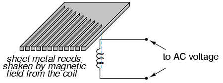 Reeds having natural vibration frequencies of 110, 112, 114, and so forth, up to 130 hertz, are mounted on the bar.
The reed with a frequency of 110 hertz is marked 55 hertz; the one with a frequency of 112 hertz is marked 56 hertz; the one with a frequency of 120 hertz is marked 60 hertz; and so forth. When the coil is energized with a current having a frequency between 55 and 65 hertz, all the reeds vibrate slightly, but the reed having a natural frequency closest to that of the energizing current (whose frequency is to be measured) vibrates more. The frequency is read from the scale value opposite the reed having the greatest vibration.
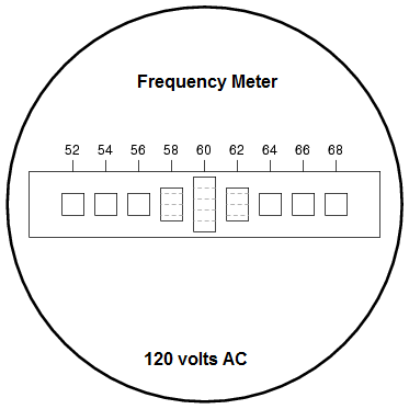 In some instruments, the reeds are the same lengths but are weighted by different amounts at the top so that they will have different natural rates of vibration. The indicator dial in the figure to the left shows an end view of the reeds.
If the current has a frequency of 60 hertz per second, the reed marked “60” hertz will vibrate the amount, as shown.
Vibrating reed meters are not precision instruments, but they are very simple and, therefore, easy to manufacture and rugged. They are often found on small engine-driven generator sets for the purpose of setting engine speed so that the frequency is somewhat close to 60 (50 in Europe) Hertz.
While reed-type meters are imprecise, their operational principle is not.
In lieu of mechanical resonance, we may substitute electrical resonance and design a frequency meter using an inductor and capacitor in the form of a tank circuit (parallel inductor and capacitor). One or both components are made adjustable, and a meter is placed in the circuit to indicate the maximum amplitude of the voltage across the two components shown in the figure below.
The adjustment knob(s) are calibrated to show resonant frequency for any given setting, and the frequency is read from them after the device has been adjusted for maximum indication on the meter. Essentially, this is a tunable filter circuit that is adjusted and then read in a manner similar to a bridge circuit (which must be balanced for a “null” condition and then read).
 This technique is popular for amateur radio operators (or at least before the advent of inexpensive digital frequency instruments called counters), especially because it doesn’t require a direct connection to the circuit. So long as the inductor and/or capacitor can intercept enough stray field (magnetic or electric, respectively) from the circuit under test to cause the meter to indicate, it will work.
In frequency, as in other types of electrical measurement, the most accurate means of measurement are usually those where an unknown quantity is compared against a known standard, the basic instrument doing nothing more than indicating when the two quantities are equal to each other.
This is the basic principle behind the DC (Wheatstone) bridge circuit, and it is a sound metrological principle applied throughout the sciences. If we have access to an accurate frequency standard (a source of AC voltage holding very precisely to a single frequency), then the measurement of any unknown frequency, by comparison, should be relatively easy.
For that frequency standard, we turn our attention back to the tuning fork, or at least a more modern variation of it called the quartz crystal. Quartz is a naturally occurring mineral possessing a very interesting property called piezoelectricity.
Piezoelectric materials produce a voltage across their length when physically stressed and will physically deform when an external voltage is applied across their lengths. This deformation is very slight in most cases, but it does exist.
Quartz rock is elastic (springy) within that small range of bending, which an external voltage would produce, which means that it will have a mechanical resonant frequency of its own capable of being manifested as an electrical voltage signal.
In other words, if a chip of quartz is struck, it will “ring” with its own unique frequency determined by the length of the chip, and that resonant oscillation will produce an equivalent voltage across multiple points of the quartz chip, which can be tapped into by wires fixed to the surface of the chip. In a reciprocal manner, the quartz chip will tend to vibrate most when it is “excited” by an applied AC voltage at precisely the right frequency, just like the reeds on a vibrating-reed frequency meter.
Chips of quartz rock can be precisely cut for desired resonant frequencies, and that chip is mounted securely inside a protective shell with wires extending for connection to an external electric circuit.

When packaged as such, the resulting device is called a crystal (or sometimes “xtal”). Electrically, that quartz chip is equivalent to a series LC resonant circuit.
The dielectric properties of quartz contribute an additional capacitive element to the equivalent circuit.
The “capacitance” and “inductance” shown in series are merely electrical equivalents of the quartz’s mechanical resonance properties: they do not exist as discrete components within the crystal.
The capacitance shown in parallel due to the wire connections across the dielectric (insulating) quartz body is real, and it has an effect on the resonant response of the whole system.
A full discussion on crystal dynamics is not necessary here, but it needs to be understood about this resonant circuit equivalence and how it can be exploited within an oscillator circuit to achieve an output voltage with a stable, known frequency.
Crystals, as resonant elements, typically have much higher “Q” (quality) values than tank circuits built from inductors and capacitors, principally due to the relative absence of stray resistance, making their resonant frequencies very definite and precise. Because the resonant frequency is solely dependent on the physical properties of quartz (a very stable substance, mechanically), the resonant frequency variation over time with a quartz crystal is very, very low.
This is how quartz movement watches obtain their high accuracy: by means of an electronic oscillator stabilized by the resonant action of a quartz crystal. For laboratory applications, though, even greater frequency stability may be desired.
To achieve this, the crystal in question may be placed in a temperature-stabilized environment (usually an oven), thus eliminating frequency errors due to thermal expansion and contraction of the quartz. For the ultimate in a frequency standard, though, nothing discovered thus far surpasses the accuracy of a single resonating atom.
This is the principle of the so-called atomic clock, which uses an atom of mercury (or cesium) suspended in a vacuum, excited by outside energy, to resonate at its own unique frequency. The resulting frequency is detected as a radio-wave signal, forming the basis for the most accurate clocks known to humanity.
National standards laboratories around the world maintain a few of these hyper-accurate clocks and broadcast frequency signals based on those atoms’ vibrations for scientists and technicians to tune in and use for frequency calibration purposes.
Now we get to the practical part: once we have a source of accurate frequency, how do we compare that against an unknown frequency to obtain a measurement?
One way is to use a CRT as a frequency-comparison device.
 Cathode Ray Tubes typically have means of deflecting the electron beam in the horizontal and vertical axes.
If metal plates are used to deflect the electrons electrostatically, there will be a pair of plates to the left and right of the beam as well as a pair of plates above and below the beam.
If we allow one AC signal to deflect the beam up and down (connect that AC voltage source to the “vertical” deflection plates) and another AC signal to deflect the beam left and right (using the other pair of deflection plates), patterns will be produced on the screen of the CRT indicative of the ratio of these two AC frequencies.
These patterns are called Lissajous figures and are a common means of comparative frequency measurement in electronics.
If the two frequencies are the same, we will obtain a simple figure on the screen of the CRT, the shape of that figure being dependent upon the phase shift between the two AC signals.
Here is a sampling of Lissajous figures for two sine-wave signals of equal frequency, shown as they would appear on the face of an oscilloscope (an AC voltage-measuring instrument using a CRT as its “movement”).
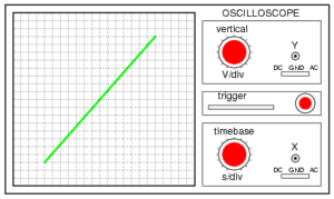
The first picture is of the Lissajous figure formed by two AC voltages perfectly in phase with each other:
Lissajous figure: same frequency, zero degrees phase shift.
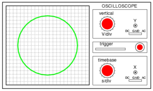
If the two AC voltages are not in phase with each other, a straight line will not be formed. Rather, the Lissajous figure will take on the appearance of an oval, becoming perfectly circular if the phase shift is exactly 90degrees between the two signals and if their amplitudes are equal:
Lissajous figure: same frequency, 90 or 270 degrees phase shift.

Finally, if the two AC signals are directly opposing one another in phase (180-degree shift), we will end up with a line again, only this time it will be oriented in the opposite direction:
Lissajous figure: same frequency, 180 degrees phase shift.
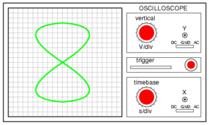
When we are faced with signal frequencies that are not the same, Lissajous figures get quite a bit more complicated. Consider the following examples, and they’re given vertical/horizontal frequency ratios:
Lissajous figure: Horizontal frequency is twice that of vertical.
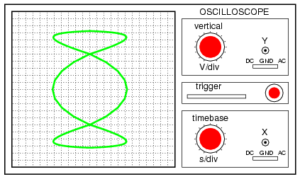
The more complex the ratio between horizontal and vertical frequencies, the more complex the Lissajous figure. Consider the following illustration of a 3:1 frequency ratio between horizontal and vertical:
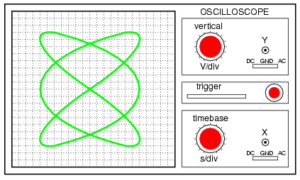
Lissajous figure: Horizontal frequency is three times that of vertical.
. . . and a 3:2 frequency ratio:
Horizontal = 3
Vertical = 2
Lissajous figure: Horizontal/Vertical frequency ratio is 3:2.
In cases where the frequencies of the two AC signals are not exactly a simple ratio of each other (but close), the Lissajous figure will appear to “move,” slowly changing orientation as the phase angle between the two waveforms rolls between 0o and 180 degrees. If the two frequencies are locked in an exact integer ratio between each other, the Lissajous figure will be stable on the view screen of the CRT.
The physics of Lissajous figures limits their usefulness as a frequency-comparison technique to cases where the frequency ratios are simple integer values (1:1, 1:2, 1:3, 2:3, 3:4, etc.). Despite this limitation, Lissajous figures are a popular means of frequency comparison wherever an accessible frequency standard (signal generator) exists.
Moving-Disk Frequency Meter
Moving-disk frequency meters are most commonly out-of-circuit meters. They can be used to spot-check the frequency of power sources or equipment signals. A simplified moving-disk frequency meter is shown in the figure below.
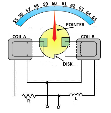 One coil tends to turn the disk clockwise and the other counterclockwise.
Magnetizing coil A is connected in series with a large value of resistance. Coil B is connected in series with a large inductance, and the source supplies the two circuits in parallel.
For a given voltage, the current through coil A is practically constant. However, the current through coil B varies with the frequency. The inductive reactance is greater at a higher frequency, and the current through coil B is less; the reverse is true at a lower frequency.
The disk turns in the direction determined by the stronger coil. A perfectly circular disk would tend to turn continuously. This is undesirable, so the disk is constructed to turn only a certain amount clockwise or counterclockwise about the center position, commonly marked as 60 hertz on commercial equipment.
To prevent the disk from turning more than the desired amount, the left half of the disk is mounted so that when motion occurs, the same amount of disk area will always be between the poles of coil A. Therefore, the force produced by coil A to rotate the disk is constant for a constant applied voltage.
The right half of the disk is offset, as shown in the figure. When the disk rotates clockwise, an increasing area will come between the poles of coil B; when it rotates counterclockwise, a decreasing area will come between the poles of coil B.
The greater the area between the poles, the greater will be the disk current and the force tending to turn the disk.
If the frequency applied to the frequency meter should decrease, the reactance offered by L would decrease, and the field produced by coil B would increase. The field produced by coil A would remain the same.
Thus, the force produced by coil B would tend to move the disk and the pointer counterclockwise until the area between the poles was reduced enough to make the two forces equal. The scale is calibrated to indicate the correct frequency.
If the frequency is constant and the voltage is changed, the currents in the two coils and the opposing forces change by the same amount. Thus, the indication of the instrument is not affected by a change in voltage.
Current Clamp (Clamp Meter)
A current clamp or probe is an electrical device with two jaws that open to clamp around an electrical conductor. This allows the properties of the electric current in the conductor to be measured without having to make physical contact with it or disconnect it for insertion through the probe.
Current clamps are usually used to read the magnitude of a sinusoidal current (as invariably used in alternating current (AC) power distribution systems), but the phase and waveform are available in conjunction with more advanced instrumentation.
Very high alternating currents (1000 A and more) are easily read with an appropriate meter; direct currents and very low AC currents (milliamperes) are more difficult to measure.
Types
Current transformer
A common form of current clamp comprises a split ring made of ferrite or soft iron. A wire coil is wound around one or both halves, forming one winding of a current transformer. The conductor around which it is clamped forms the other winding.
Like any transformer, this type works only with AC or pulse waveforms, with some examples extending into the megahertz range. When measuring current, the subject conductor forms the primary winding, and the coil forms the secondary.
This type may also be used in reverse to inject current into the conductor, for example, in EMC susceptibility testing to induce an interference current. Usually, the injection probe is specifically designed for this purpose. In this mode, the coil forms the primary and the test conductor the secondary.
Iron vane
In the iron vane type, the magnetic flux in the core directly affects a moving iron vane, allowing both AC and DC to be measured, and gives a true RMS value for non-sinusoidal AC waveforms.
Due to its physical size is generally limited to power transmission frequencies up to around 100 Hz. The vane is usually fixed directly to the display mechanism of an analog (moving pointer) clamp meter.
Hall effect
The Hall effect type is more sensitive and is able to measure both DC and AC, in some examples up to the kilohertz (thousands of hertz) range. This type was often used with oscilloscopes and high-end computerized digital multimeters, however, they are becoming commonplace for general use.
Clamp meter
 An electrical meter with an integral AC current clamp is known as a clamp meter, clamp-on ammeter, or tong tester.
A clamp meter measures the vector sum of the currents flowing in all the conductors passing through the probe, which depends on the phase relationship of the currents. Only one conductor is usually passed through the probe.
In particular, if the clamp is closed around a two-conductor cable carrying power to equipment, the same current flows down one conductor and up the other; the meter correctly reads a net current of zero.
As electrical cables for equipment have both insulated conductors (and possibly an earth wire) bonded together, clamp meters are often used with what is essentially a short extension cord with the two conductors separated so that the clamp can be placed around only one conductor of this extension.
The reading produced by a conductor carrying a very low current can be increased by winding the conductor around the clamp several times; the meter reading divided by the number of turns is the current, with some loss of accuracy due to inductive effects.
 Clamp meters are used by electricians, sometimes with the clamp incorporated into a general-purpose multimeter. Measuring very high currents (hundreds of amperes) with the appropriate current transformer is simple. Accurate measurement of low currents (a few milliamperes) with a current transformer clamp is more difficult.
Less-expensive clamp meters use a rectifier circuit that actually reads mean current but is calibrated to display the RMS current corresponding to the measured mean, giving a correct RMS reading only if the current is a sine wave.
For other waveforms, readings will be incorrect; when these simpler meters are used with non-sinusoidal loads, such as the ballasts used with fluorescent lamps or high-intensity discharge lamps, or most modern computer and electronic equipment, readings can be quite inaccurate.
Meters that respond to true RMS rather than mean current are described as “true RMS.” Typical hand-held Hall effect units can read currents as low as 200 mA, and units that can read down to 1 mA are available.
 The Columbia Tong test ammeter is an example of the iron vane type used for measuring large AC currents up to 1000 amperes.
The iron jaws of the meter direct the magnetic field surrounding the conductor to an iron vane that is attached to the needle of the meter. The iron vane moves in proportion to the strength of the magnetic field and thus produces a meter indication proportional to the current.
This type of ammeter can measure both AC and DC currents and provides a true RMS current measurement of non-sinusoidal or distorted AC waveforms. Interchangeable meter movements can be installed in the clamping assembly to provide various full-scale current values up to 1000 amperes.
The iron vane is in a small cylinder that is inserted in a space at the hinged end of the clamp-on jaws. Several jaw sizes are available for clamping around large conductors and bus bars up to 4 1⁄2 inches (110 mm) wide.
As the image shows, the scale is non-linear and unsuitable for measuring low currents, with currents of less than half the full-scale deflection crammed into a short section of the dial.
Power meter, energy analyzer
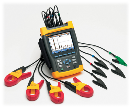
Clamp probes are used with some meters to measure electrical power and energy. The clamp measures the current and other circuitry the voltage; the true power is the product of the instantaneous voltage and current integrated over a cycle.
Comprehensive meters designed to measure many parameters of electrical energy (power factor, distortion, instantaneous power as a function of time, phase relationships, etc.), energy analyzers use this principle.
A single clamp is used for single-phase measurements; with an appropriate instrument with three clamps, measurements may be made on three-phase power systems. An important electrical quantity with no equivalent in DC circuits is frequency.
Frequency measurement is very important in many applications of alternating current, especially in AC power systems designed to run efficiently at one frequency and one frequency only.
If an electromechanical alternator is generating the AC, the frequency will be directly proportional to the shaft speed of the machine, and frequency could be measured simply by measuring the speed of the shaft.
If frequency needs to be measured at some distance from the alternator, other means of measurement will be necessary.